
Detonator defect automatic optic inspection machine

An automatic optical detection and detonator technology, applied in the direction of optical testing defects/defects, can solve problems such as false detection or missed detection, low production efficiency, easy fatigue, etc., achieve stable and accurate detection results, reduce the difficulty of defect detection, and eliminate background interference effect

Inactive Publication Date: 2015-06-03
长沙市伟视创图像技术有限公司
View PDF6 Cites 9 Cited by
  • Summary
  • Abstract
  • Description
  • Claims
  • Application Information

AI Technical Summary

Problems solved by technology

The manual inspection method is greatly affected by factors such as artificial subjective emotions and physical fluctuations. Workers are very prone to fatigue when working continuously, and can only be adjusted by shifts. Manual terminal inspection of appearance defects will cause unreliable inspection results. , it is easy to cause false detection or missed detection, low production efficiency, and increase the production cost of the enterprise
Detonators are dangerous goods strictly controlled by the state. If unqualified products flow into the market, it will harm the interests of consumers. If a safety accident caused by a defective detonator occurs, it will even endanger the personal safety of the detonator user.

Method used


Image

  • Detonator defect automatic optic inspection machine
  • Detonator defect automatic optic inspection machine
  • Detonator defect automatic optic inspection machine

Examples


Embodiment Construction

[0019] Below in conjunction with accompanying drawing, the present invention is described in further detail:

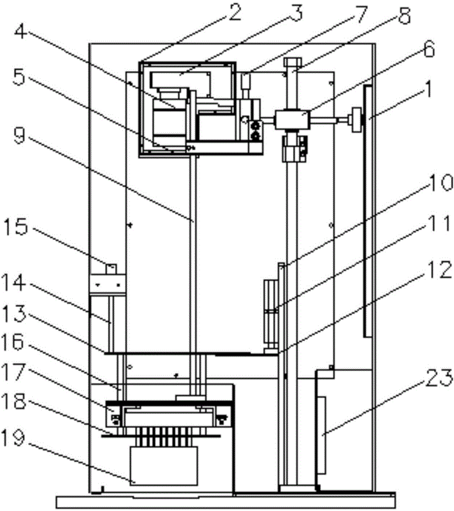
[0020] Examples, such as figure 1 , figure 2 , image 3 , Figure 4 , Figure 5 As shown, the detonator defect intelligent optical detection machine of the present invention is equipped with a two-dimensional direction adjustment mechanism 6 on the frame 1 and connected to the image acquisition system 2. The image acquisition system 2 is an intelligent industrial camera equipped with an embedded detonator defect automatic identification software program. 3. The industrial lens 4 and the antireflection coated optical glass 5 are assembled on the frame 8 of the image acquisition system. There is a working distance fine-tuning mechanism 7 on the frame 8 of the image acquisition system, and an industrial camera is installed on the frame 8 of the image acquisition system. Dust-proof sealed machine cover, industrial camera dust-proof sealed machine cover is installed w...


PUM

PropertyMeasurementUnit
wavelengthaaaaaaaaaa
diameteraaaaaaaaaa
heightaaaaaaaaaa

Abstract

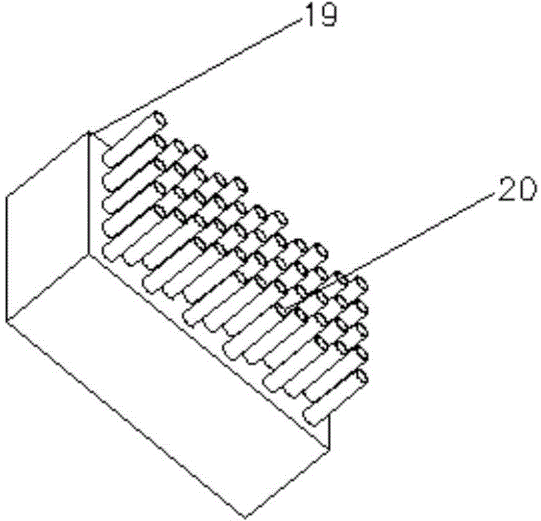
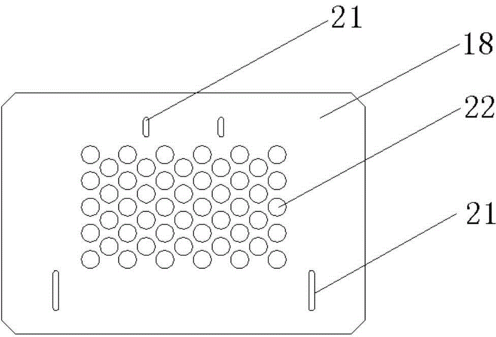
The invention relates to the product defect automatic online detection technology and in particular relates to a detonator defect automatic optic inspection machine. A two-dimensional direction adjusting mechanism (6) arranged on a rack (1) is connected with an image acquisition system (2), a 0-degree four-side strip light source assembly (17) is connected under the image acquisition system (2) by an adjusting pull rod (9), a detonator mold base (19) provided with a detonator (20) is positioned under the 0-degree four-side strip light source assembly (17), a driving cylinder (11) arranged on the rack (1) is connected with a two-dimensional direction adjusting mechanism (13) and drives a detonator backlight plate (18) to move up and down by a guide rod (16), a locating sleeve hole (22) consistent with the detonator mold base (19) is formed on the detonator backlight plate (18) and sleeves the detonator (20), a communication and cylinder driving control circuit module (23) is arranged on the rack (1). The detonator defect automatic optic inspection machine has high detection efficiency, and stable and accurate detection result, ensures that the detection result is objective and reliable, is suitable for online matched use and detection of the detonator filling production line, and is a brand-new high-efficiency detonator defect foreign matter automatic optical image detection machine.

Description

technical field [0001] The invention relates to an online automatic detection technology for product defects, in particular to an automatic optical detection machine for detonator defects. Background technique [0002] In the production and assembly process of detonators, it is necessary to quickly detect defects such as collapse, tearing, curling, and foreign objects in the nozzle of the nozzle and body of the detonator. By inventing an automatic detection machine, it cooperates with the detonator production line. The waste tube removal system achieves the linkage of the detonator assembly production line integrating detection and removal, and realizes the online removal of unqualified detonators. At present, all domestic detonator production lines have a relatively high degree of automation in the process of detonator powder filling and cap pressing, but the detection of defective detonators is still done by manual visual inspection. Generally, a detonator production and a...

Claims


Application Information

Patent Timeline
Patent Type & Authority Applications(China)
IPC IPC(8): G01N21/88
Inventor 吴士旭王志坚包崇兵谢纪东
Owner 长沙市伟视创图像技术有限公司
Learn More