Broadband micro-strip antenna array coupling structure

A technology of microstrip antenna and coupling structure, which is applied in the direction of antenna, radiating element structure, electrical components, etc., can solve the problems of time-consuming and laborious, large access, error, etc., to reduce the side lobe level, speed up the design process, Eliminate the effect of cumbersome procedures

Inactive Publication Date: 2015-06-03
LINGBAYI ELECTRONICS GRP
View PDF2 Cites 15 Cited by
  • Summary
  • Abstract
  • Description
  • Claims
  • Application Information

AI Technical Summary

Problems solved by technology

It has two main disadvantages. The first is that it increases the difficulty of accurate analysis and design, because at this time two different dielectric substrates are involved, so the simple model of the conventional single-layer microstrip antenna is no longer applicable.
Second, since the feeder and the patch are in different planes, the feeder is no longer in an open plane, making it difficult to connect the relevant components to the feeder circuit
However, this classic design method does not consider the influence of mutual coupling, so the energy amplitude distribution actually fed to the antenna unit port through the power division network has an error with t

Method used


Image

  • Broadband micro-strip antenna array coupling structure
  • Broadband micro-strip antenna array coupling structure

Examples


Embodiment Construction

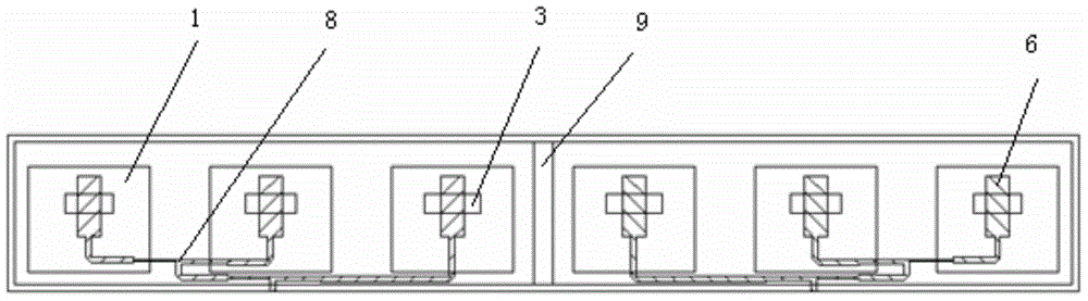
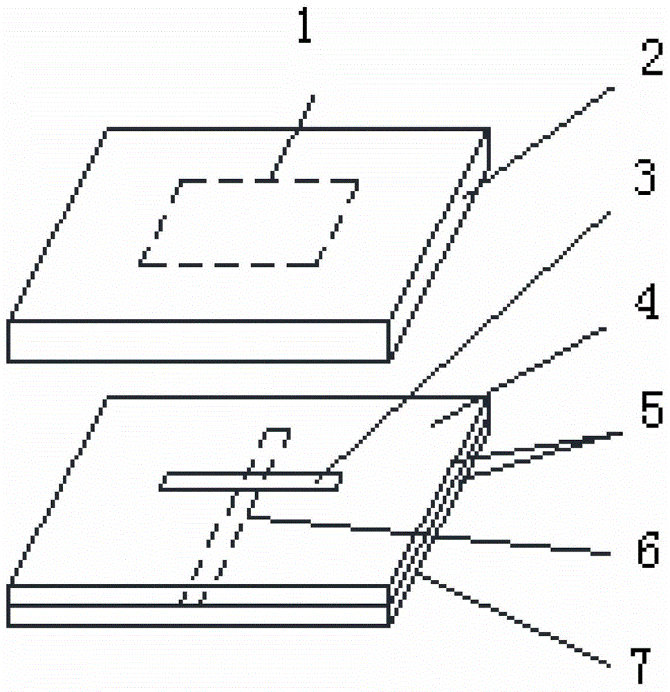
[0014] refer to figure 1. A wideband microstrip antenna array feeding coupling structure includes a microstrip patch antenna array body. The microstrip patch antenna array body is composed of several antenna radiation units provided with coupling slots, the length setting mode of each antenna radiation unit coupling slot is to decrease from the middle to both ends on the array body, and the same length coupling slots are provided. The antenna radiating elements are arranged in pairs on the microstrip patch antenna array body. The microstrip patch antenna array body is composed of several longitudinally arranged antenna radiation units arranged on the dielectric support 9, each antenna radiation unit is provided with a coupling groove 3 below the radiation patch 1, and each radiation patch The coupling slots 3 below 1 are arranged sequentially from left to right, and the length of the coupling slots of each antenna radiating unit is along the length direction of the microstri...


PUM


Abstract

The invention discloses a broadband micro-strip antenna array coupling structure, and aims to provide a micro-strip patch antenna array, which is simple in structure, is conveniently and quickly debugged and can effectively reduce side-lobe levels of antennae. According to the technical scheme, a micro-strip patch antenna array body consists of a plurality of antenna radiation units longitudinally arranged on a dielectric support, wherein a coupling groove is formed below a radiation patch of each antenna radiation unit; the length of the coupling groove of each antenna radiation unit is progressively decreased from middle to two ends, so that a gradually variable coupling groove length aperture coupling form is achieved; the antenna radiation units with the coupling grooves which are equal in length are arranged in pairs on the array body; the lengths of the coupling grooves which are symmetrically formed in pairs from left to right are equal; the patch of each antenna radiation unit feeds through a unit feeder perpendicularly passing through the corresponding coupling groove. According to the broadband micro-strip antenna array coupling structure, the lengths of the coupling grooves are progressively decreased from middle to two ends, so that excitation current for the coupling of the feeders to the patches is changed, and the side-lobe levels of the antennae are reduced.

Description

technical field [0001] The invention relates to a microstrip antenna array structure, in particular to a small aperture-coupled microstrip patch antenna array and a quick debugging method for the antenna array. Background technique [0002] Microstrip antenna is a new type of antenna successfully developed in the early 1970s. Compared with common microwave antennas, it has small size, light weight, low profile, conformal with the carrier, simple manufacture, low cost, and easy integration with microstrip antennas. Circuit integration and microstrip antennas with the same structure can form an array to obtain high gain and other characteristics. At present, the microstrip antenna array composed of the microstrip patch antenna as the radiation unit has been widely used in the radio equipment of the aircraft and the ground handheld system. Due to the inherent disadvantages of narrow bandwidth and low power of microstrip antennas, traditionally, the working bandwidth of microst...

Claims


Application Information

Patent Timeline
IPC IPC(8): H01Q1/38H01Q13/08
Inventor 陈斌赵玉国李富军史浩曾传宝
Owner LINGBAYI ELECTRONICS GRP
Why Eureka
Try Eureka