Magnetic field balance distribution type wireless power transmission system based on magnetic resonant coupling

A technology of wireless power transmission and magnetic resonance coupling, which is applied in the direction of electromagnetic wave systems, electrical components, circuit devices, etc., can solve the problems of not meeting the requirements of humanization, the decline of transmission efficiency, and the uneven distribution of magnetic field, etc., and achieve a small decline in transmission efficiency , under-coupling mitigation, and the effect of saving processing costs

Active Publication Date: 2015-06-03
CHENGDU SPROUTING TECH CO LTD
View PDF5 Cites 10 Cited by
  • Summary
  • Abstract
  • Description
  • Claims
  • Application Information

AI Technical Summary

Problems solved by technology

Both the transmitting end and the receiving end of the currently disclosed wireless power transmission system based on magnetic resonance coupling adopt a single resonant coil structure, and the power transmission is realized through the same-frequency magnetic resonance coupling between the resonant coils at the receiving and receiving ends; The wireless power transmission system designed with a single resonant coil will lead to an unbalanced magnetic field distribution at the receiving end, makin...

Method used


Image

  • Magnetic field balance distribution type wireless power transmission system based on magnetic resonant coupling
  • Magnetic field balance distribution type wireless power transmission system based on magnetic resonant coupling
  • Magnetic field balance distribution type wireless power transmission system based on magnetic resonant coupling

Examples


Embodiment 1

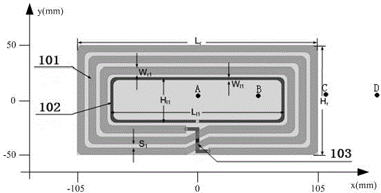
[0047] Embodiment 1: adopt figure 1 shown in the transmitter and Figure 5 , Figure 6 The receiving end shown is a rectangular flat-panel wireless power transfer system that can be used for laptops, tablet computers, LED lighting equipment, and speakers.

[0048] The structural diagrams of the transmitting module and the receiving module are as follows: figure 1 and Figure 5 , Figure 6 As shown in , there is no metal sheet attached to the back.

[0049] according to figure 1 and Figure 5 , Figure 6 The symbol identification in the structure diagram shown in , combined with the actual application requirements, the design in this embodiment adopts the following geometric parameters and electrical parameters:

[0050] Table 1 Geometric parameters and electrical parameters of the transmitting module and receiving module in Embodiment 1

[0051] symbol identification

Ranges)

L r

210(mm)

H r

100(mm)

W r1

6-7(mm)

W l...

Embodiment 2

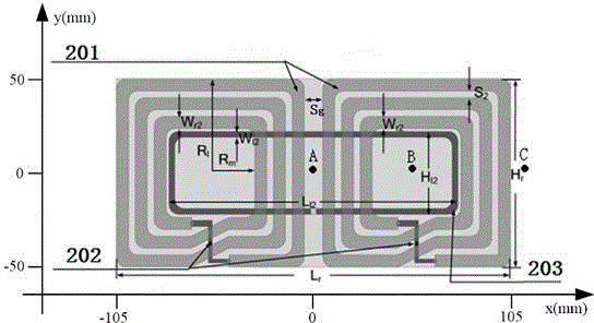
[0059] Embodiment 2: adopt figure 2 shown in the transmitter and Figure 9 , Figure 10 The shown receiving end is a magnetic field balanced distributed wireless power transmission system that can be used for portable computers, tablet computers, LED lighting equipment and sound boxes.

[0060] The structural diagrams of the transmitting module and the receiving module are as follows: figure 2 and Figure 9 , Figure 10 As shown in , there is no metal sheet attached to the back.

[0061] according to figure 2 and Figure 9 , Figure 10 The symbol identification in the structure diagram shown in , combined with the actual application requirements, the design in this embodiment adopts the following geometric parameters and electrical parameters:

[0062] Table 2 Geometric parameters and electrical parameters of the transmitting module and receiving module in Embodiment 2

[0063] symbol identification

Ranges)

L r

210(mm)

H r

100(mm...

Embodiment 3

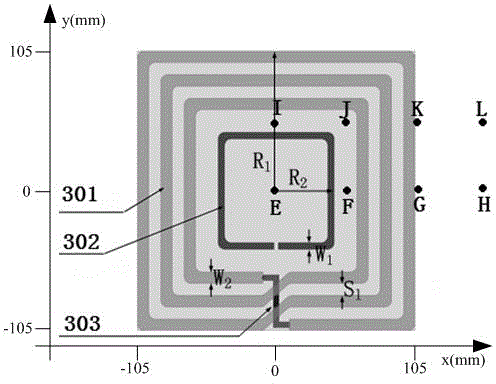
[0072] Embodiment 3: adopt image 3 shown in the transmitter and Figure 5 , Figure 6 The receiving end shown is a square-shaped, flat-panel wireless power transfer system that can be used for laptops, tablets, LED lighting equipment, and speakers.

[0073] The structural diagrams of the transmitting module and the receiving module are as follows: image 3 and Figure 5 , Figure 6 As shown in , there is no metal sheet attached to the back.

[0074] according to image 3 and Figure 5 , Figure 6 The symbol identification in the structure diagram shown in , combined with the actual application requirements, the design in this embodiment adopts the following geometric parameters and electrical parameters:

[0075] Table 4 Geometric parameters and electrical parameters of the transmitting module and receiving module in Embodiment 3

[0076] symbol identification

Ranges)

R 1

105(mm)

R 2

42-46(mm)

W 1

4-6(mm)

W 2

4-...


PUM

PropertyMeasurementUnit
Lengthaaaaaaaaaa
Widthaaaaaaaaaa
Lengthaaaaaaaaaa

Abstract

The invention discloses a magnetic field balance distribution type wireless power transmission system based on magnetic resonant coupling. An emitting end of the system adopts an array-type resonant coil structure and a feeding mode for simultaneously driving all resonant coils by a single excitation coil, and magnetic resonance between resonant coils of a receiving end and a resonant coil array of the emitting end as well as magnetic fields uniformly distributed at the receiving end are realized. While the transmission efficiency higher than 65% is realized, the axial and transverse receiving ranges of the receiving end are expanded and the stability of wireless power transmission is improved. The emitting end and the receiving end adopt planar structures and can be processed through printed circuit boards, a rectifying and voltage-stabilizing circuit is integrated in a blank area of the circuit board of the receiving end, 5-12 V direct-current voltage can be output, and the size of the receiving end can be reduced to 50*50*1 mm<3>. The wireless power transmission system is suitable for various coil structures such as a rectangular coil structure and a square coil structure, and can be applied to one-to-one and one-to-many wireless power transmission of portable computers, tablet computers, LED illumination equipment, sound boxes, mobile communication terminal and small-sized consumer electronics.

Description

technical field [0001] The invention relates to a magnetic field balanced distributed wireless power transmission system based on magnetic resonance coupling, which belongs to the technical field of wireless power transmission. Background technique [0002] With the continuous development of electronic information technology and automation control technology, various home appliances, consumer electronics, mobile communication equipment, etc. have been widely popularized. However, traditional household appliances rely Electronic devices with built-in batteries also need a wired connection between the charging cable and the power outlet for charging, so we can see wires that provide power supply for these electronic devices everywhere. These wires not only occupy our activity space, limit the convenience of equipment use, but also create hidden dangers for safe use of electricity. Therefore, with the growing demand for portable devices and green energy systems that can be use...

Claims


Application Information

Patent Timeline
IPC IPC(8): H02J17/00H02J50/12
CPCH02J5/005
Inventor 喻易强陈志璋彭思培法瑞德·朱拉里
Owner CHENGDU SPROUTING TECH CO LTD
Why Eureka
Try Eureka