A gear processing machine tool

A technology for processing machine tools and gears, applied in metal processing machinery parts, metal processing, metal processing equipment, etc., can solve the problems of inconvenient observation by operators, inconvenient loading and unloading of workpieces, and large changes in the position of machining points of machine tools, so as to facilitate the loading and unloading of workpieces. And the protection of the machine tool, to ensure stability and reliability, the effect of the compact structure of the machine tool

Active Publication Date: 2019-02-12
HUNAN ZDCY (ZHONGDA CHUANG YUAN) CNC EQUIP CO LTD
View PDF8 Cites 0 Cited by
  • Summary
  • Abstract
  • Description
  • Claims
  • Application Information

AI Technical Summary

Problems solved by technology

[0006] Although the CNC bolt bevel gear processing machine tool converts the complex mechanical structure into software control and realizes the informatization and intelligence of spiral bevel gear processing, it still does not fully utilize the role of CNC technology, and there are the following problems:
[0007] First, since the column 14 is fixed on the bed 11, in order to allow the tool 18 on the tool box 16 installed on the horizontal slide table 15 to process the workpiece 13, it is necessary to extend the tool spindle 17 very long, thereby increasing the impact of the tool 18. The overhang ratio between the force point and the bearing support distance of the tool spindle 17 leads to low rigidity of the tool spindle 17, which affects the processing of the workpiece 13;
[0008] Second, when the machine tool structure is processing left-handed and right-handed spiral bevel gears, the machining points of the machine tool are respectively at the upper and lower positions of the workpiece 13, resulting in a large change in the position of the machining points of the machine tool, and the stroke of the tool box 16 in the Y-axis direction is longer. When the position of the processing point is high, it affects the overall processing rigidity of the machine tool, and it is inconvenient for the operator to observe during the processing;
[0009] Third, during the processing of this machine tool structure, the X-axis slide plate 12 must move along the X-axis direction, so that the X-axis guide rail 20 is installed on the bed 11, and the chip removal groove 19 cannot be opened to the entire processing area, resulting in the falling of processing chips To the bed on the 12th side of the X-axis slide plate; although armor-style steel protection can be installed on the side of the workpiece box, it is not easy to clean the chips falling on the steel protection surface, and a large amount of chips will still accumulate on the bed when milling teeth 11. The development direction of spiral bevel gear milling is dry cutting, that is, no coolant is added during processing, the cutting speed is fast, and the heat is taken away by the cutting chips. If a large number of cutting chips accumulate on the bed 11, it is easy to cause the heat of the machine tool deformation;
[0010] Fourth, the three linear motion axes X, Y, and Z of the machine tool structure are relatively scattered, resulting in a large footprint of the machine tool, inconvenient loading and unloading of workpieces, and difficult protection

Method used


Image

  • A gear processing machine tool
  • A gear processing machine tool
  • A gear processing machine tool

Examples


Embodiment Construction

[0049] The core of the present invention is to provide a gear processing machine tool with stable and reliable processing performance, small footprint and easy protection.

[0050] In order to enable those skilled in the art to better understand the solution of the present invention, the present invention will be further described in detail below in conjunction with the accompanying drawings and specific embodiments.

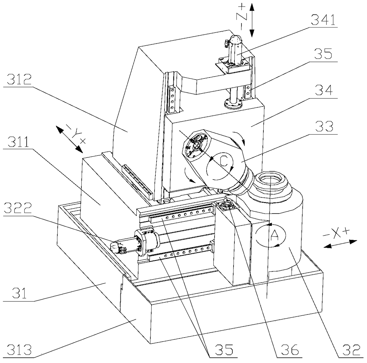
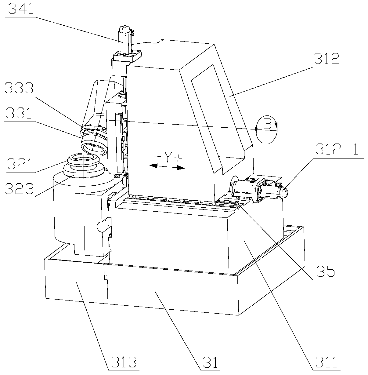
[0051] Please refer to Figure 2-3 , figure 2 It is a schematic structural diagram of the first embodiment of the gear processing machine tool provided by the present invention; image 3 for figure 2 A structural schematic diagram of another angle of the gear machining machine shown in .

[0052] In this embodiment, the gear processing machine tool may be a gear milling machine or a gear grinding machine, including a bed 31 , a workpiece box 32 , a tool box 33 and a B-axis box 34 .

[0053]The workpiece box 32 is movably installed on the bed 31 along the f...


PUM


Abstract

The invention discloses a gear processing lathe. The gear processing lathe comprises a lathe bed, a stand column arranged on the lathe bed, a workpiece box and a B shaft box, wherein the workpiece box is movably mounted on the lathe bed in a first horizontal direction, and the axis of a workpiece revolving shaft is parallel to a vertical direction; the B shaft box is movably mounted on the stand column in the vertical direction, the axis of a B shaft is parallel to a second horizontal direction which is perpendicular to the first horizontal direction, a cutter box is mounted at one end close to the workpiece box, and the axis of a cutter revolving shaft of the cutter box is perpendicular to the second horizontal direction; for the cutter box and the workpiece box, one can approach to or be far away from the other in the second horizontal direction. The gear processing lathe is compact in structure and occupies a small area; the cutter revolving box and the workpiece revolving box can make relative movement, the cutter revolving shaft can process workpieces without extending out of the cutter box too long, so that the rigidity of the cutter revolving shaft is effectively guaranteed; processing points are distributed on the left and the right of a workpiece, so that the processing stability and the processing reliability of the workpiece are guaranteed.

Description

technical field [0001] The invention relates to the technical field of numerical control processing equipment, in particular to a gear processing machine tool for processing spiral bevel gears. Background technique [0002] The existing spiral bevel gear processing equipment mainly includes mechanical spiral bevel gear processing machine tools and numerically controlled spiral bevel gear processing machine tools. Among them, the structure and adjustment of mechanical spiral bevel gear processing machine tools are the most complicated. Therefore, the application of CNC bolt bevel gear processing machine tools is becoming more and more extensive. [0003] Please refer to figure 1 , figure 1 It is a structural schematic diagram of the existing CNC spiral bevel gear processing machine tool. [0004] Such as figure 1 As shown, the CNC spiral bevel gear processing machine tool includes a bed 11, one side of the upper end of the bed 11 is provided with an X-axis slide plate 12,...

Claims


Application Information

Patent Timeline
Patent Type & Authority Patents(China)
IPC IPC(8): B23F9/02B23F9/08B23Q1/26B23Q5/00
Inventor 张春晖李锡晗丁志文
Owner HUNAN ZDCY (ZHONGDA CHUANG YUAN) CNC EQUIP CO LTD
Why Eureka
Try Eureka