

Position sensitive intelligent air foot
A gas foot and sensitive technology, applied in the field of position-sensitive intelligent gas foot, can solve the problems of complex system and high cost, and achieve the effect of reducing development difficulty and cost, low cost and high reliability
- Summary
- Abstract
- Description
- Claims
- Application Information
AI Technical Summary
Problems solved by technology
Method used
Image

Examples
specific Embodiment approach 1
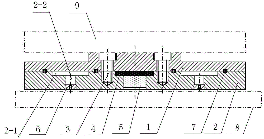
[0021] Specific implementation mode one: the following combination figure 1 and figure 2 Describe this embodiment, the position-sensitive smart air foot described in this embodiment includes a gas sealing plate 1, an air foot substrate 2, fasteners 3, a processing circuit board 4, a photoelectric position sensor 5, and N throttle nozzles 6 and two O-rings 7, N=3,4,5,6,7,8,9;
[0022] The air sealing plate 1 and the air foot base plate 2 are connected together by fasteners 3;
[0023] An annular air cavity 2-1 is arranged on the upper surface of the air foot substrate 2, the upper surface is the surface connected to the air sealing plate 1, and N air flow holes 2-2 are uniformly arranged on the lower surface of the air foot substrate 2, Each air flow hole 2-2 communicates with the annular air cavity 2-1, and the central axes of N air flow holes 2-2 correspond to the center of the annular air cavity 2-1 respectively; each air flow hole 2-2 The bottom end is interference fitt...
specific Embodiment approach 2
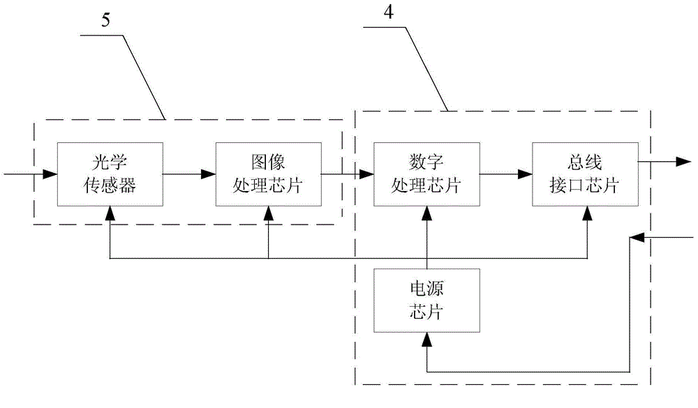
[0029] Specific implementation mode two: the following combination figure 2 Illustrate this embodiment, this embodiment will further illustrate embodiment one, photoelectric position sensor 5 is made up of optical sensor and image processing chip; Processing circuit board 4 comprises digital processing chip and bus interface chip;
[0030] The optical sensor collects the optical image of the air bearing platform 8 at the current position, converts the optical image into a digital image, and then transmits it to the image processing chip. The image processing chip makes a difference between two adjacent digital images to obtain a motion displacement increment;
[0031] The digital processing chip integrates the movement displacement increment to obtain the current movement displacement of the air foot relative to the air bearing platform 8, and the bus interface chip converts the movement displacement into a bus form displacement, thereby obtaining the relative movement displac...
specific Embodiment approach 3
[0033] Specific implementation mode three: the following combination figure 2 This embodiment will be described. This embodiment will further describe the second embodiment. The processing circuit board 4 also includes a power supply chip.
[0034] The power supply chip is used to supply power to the optical sensor, image processing chip, digital processing chip and bus interface chip.
PUM
 Abstract
Description
Claims
Application Information