Determination method for interface heat transfer coefficient in casting process

A technology of interface heat transfer coefficient and measurement method, applied in the direction of material thermal development, etc., can solve the problem that the interface heat transfer coefficient is difficult to determine accurately

Inactive Publication Date: 2015-06-10
CENTRAL SOUTH UNIVERSITY OF FORESTRY AND TECHNOLOGY
View PDF6 Cites 16 Cited by
  • Summary
  • Abstract
  • Description
  • Claims
  • Application Information

AI Technical Summary

Problems solved by technology
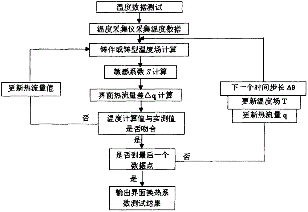
[0004] In view of the above problems, the purpose of the present invention is to provide a method for measuring the interface heat transfer coefficient in the casting process, thereby solving the problem that the interface heat transfer coefficient is difficult to accurately determine in the metal casting cooling and solidification process existing in the prior art

Method used


Image

  • Determination method for interface heat transfer coefficient in casting process
  • Determination method for interface heat transfer coefficient in casting process
  • Determination method for interface heat transfer coefficient in casting process

Examples


Embodiment 1

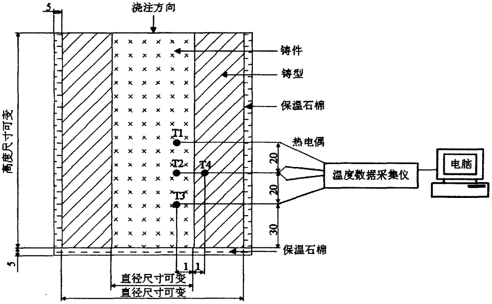
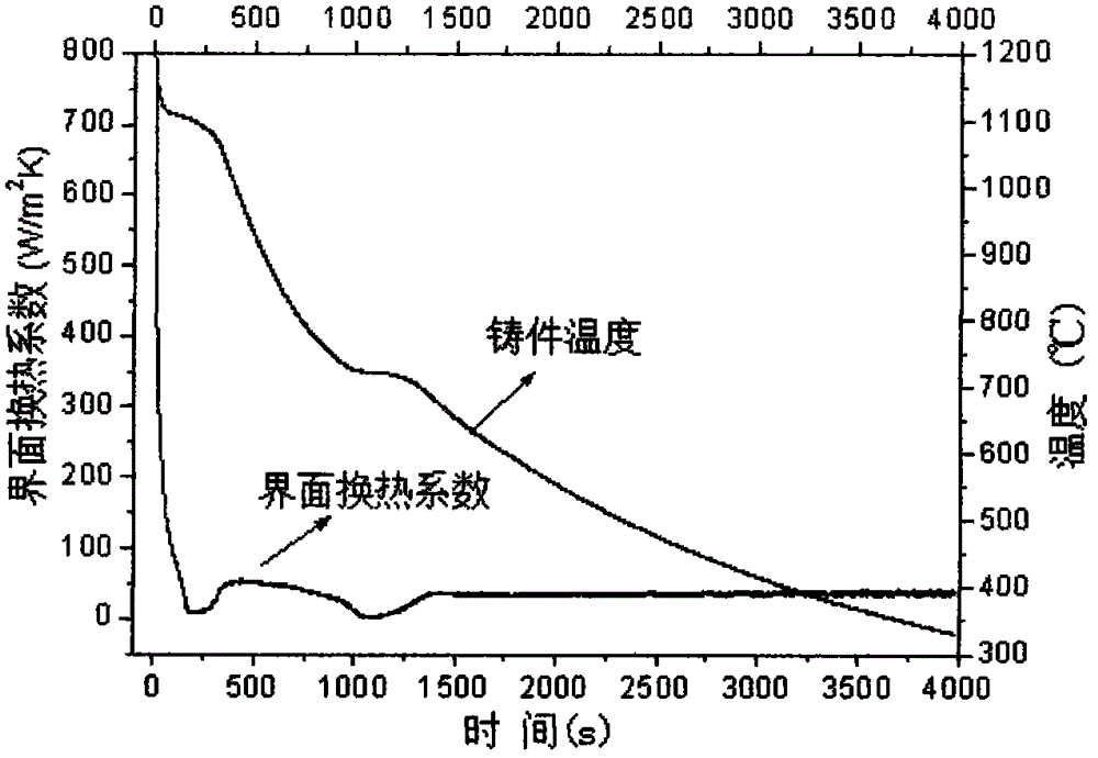
[0041] The present invention is applied in gray cast iron lost foam casting experiment, and the position that thermocouple is placed in experiment process is as follows figure 2 as shown, figure 2 In T1, T2 and T3 are the positions of temperature measurement during the experiment, respectively. In the experiment scheme, the initial mold temperature is 25°C, and the pouring temperature during the experiment is 1350°C. Considering that during lost foam casting, when the foam encounters molten metal, the gas generated by combustion will escape through the pores of the sand mold, and the asbestos used for heat insulation was removed from the outer surface of the mold during the experiment. In the casting experiment plan, the thickness of the castings is 50mm and 70mm respectively, while the thickness of the mold is 80mm, and the time interval of data collection is 0.2 seconds. Type K thermocouple wire. image 3 and Figure 4 are the measurement results of the interfacial hea...

Embodiment 2

[0043] The present invention is applied to the aluminum alloy metal mold gravity casting experiment. During the experiment, the placement position of the thermocouple is as follows: figure 2 as shown, figure 2 In T1, T2 and T3 are the temperature measurement positions during the experiment, respectively. In the experiment scheme, the pouring temperature is 730°C, and the initial mold temperature is 350°C. In order to accurately measure the heat transfer coefficient of the interface between the casting and the mold, and to avoid the influence of the external environment on the measurement accuracy when the casting is cooled and solidified, the outer surface of the mold is insulated with thermal insulation asbestos during the experiment. K-type thermocouple wire when measuring The time step of collecting data is 0.2 seconds. like Figure 5 Shown are the measured results of the interfacial heat transfer coefficient for a casting with a thickness of 50 mm. from Figure 5 I...


PUM

PropertyMeasurementUnit
thicknessaaaaaaaaaa
thicknessaaaaaaaaaa
thicknessaaaaaaaaaa

Abstract

The invention discloses a determination method for an interface heat transfer coefficient in a casting process. The determination method for the interface heat transfer coefficient in the casting process comprises the following steps that K type thermal couples with the diameter being 0.1 mm-0.5mm are arranged on the positions, 1 mm-5mm away from the cast mold surface, of a cast mold and a cavity respectively, the K type thermal couples are inserted into one end in the casting mold and one end in the casting mold cavity and protected by ceramic tubes with the diameter being 2.0 mm-10 mm, and the other ends of the casting mold and the casting mold cavity are connected to a computer; the interface heat transfer coefficient of a casting piece in the process of cooling and solidfication can be obtained by using a heat transfer recognition software according to the temperature changing data of casting piece measuring points and casting mold inner measuring points. The injection mold cold runner casting system structure is suitable for special casting processes including sand casting, die casting, evanescent mode casting, metal mold casting and pressure casting for aluminium alloy, steel, iron and other different materials.

Description

technical field [0001] The invention relates to a method for measuring interface heat transfer coefficient, in particular to a method for measuring interface heat transfer coefficient in a casting process. Background technique [0002] Casting is one of the basic processes of modern manufacturing industry and the most widely used processing and forming method at present, because of its near-net shape of the blank, it can achieve the purpose of free machining or a small amount of processing, which reduces the cost and reduces the production time to a certain extent. One of them plays a very important role in national economy and national defense construction. In recent years, with the development of computing technology, numerical simulation has become an effective means of casting solidification process control, process design and improving the quality and performance of casting products. The design of casting process has gradually moved from experience to science. Under th...

Claims


Application Information

Patent Timeline
Patent Type & Authority Applications(China)
IPC IPC(8): G01N25/20
Inventor 张立强
Owner CENTRAL SOUTH UNIVERSITY OF FORESTRY AND TECHNOLOGY
Why Eureka
Try Eureka