Gyroscopic effect demonstrator

A technology of gyroscopic effect and demonstration device, which is applied in the field of teaching aids and achieves the effects of reasonable structure, wide application fields and suitable for popularization and use.

Inactive Publication Date: 2015-06-10
SHANGHAI OCEAN UNIV
View PDF5 Cites 5 Cited by
  • Summary
  • Abstract
  • Description
  • Claims
  • Application Information

AI Technical Summary

Problems solved by technology

Therefore, it is very important to understand the basics of gyroscopes. Especially for students majoring in marine engineering and fishing boats, it is essential to learn gyroscopes. They all need to understand and master a theoretical knowledge, but it is only the theory of gyroscope effects in books. Many of the force analysis and concept descriptions are only abstract descriptions of the working phenomenon of the gyroscope, which cannot enable students to truly understand its essence. It is difficult for all students to establish a dynamic concept of the gyroscope effect theory in their minds

Method used


Image

  • Gyroscopic effect demonstrator
  • Gyroscopic effect demonstrator
  • Gyroscopic effect demonstrator

Examples


Embodiment Construction

[0027] A gyro effect demonstrator of the present invention will be further described in detail below in conjunction with the accompanying drawings.

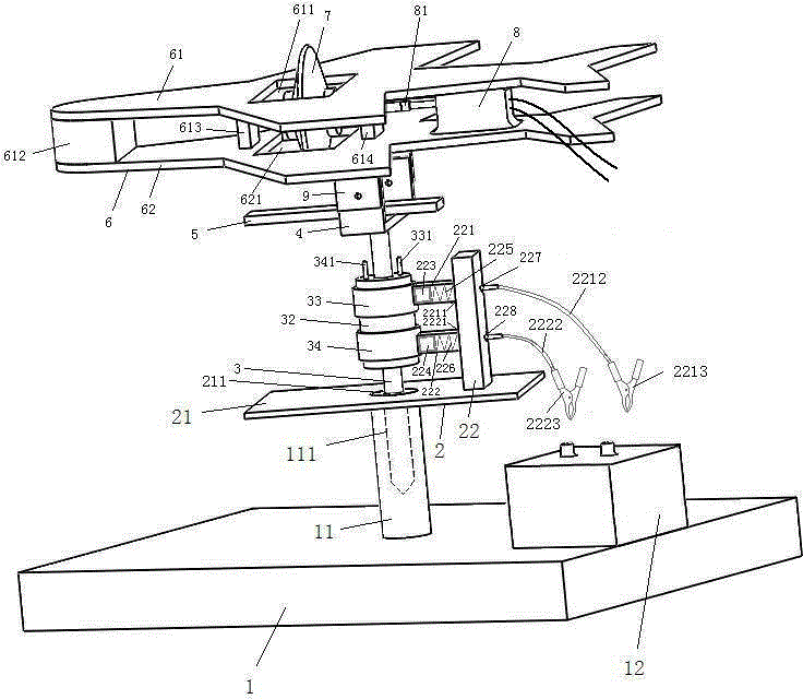
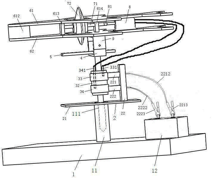
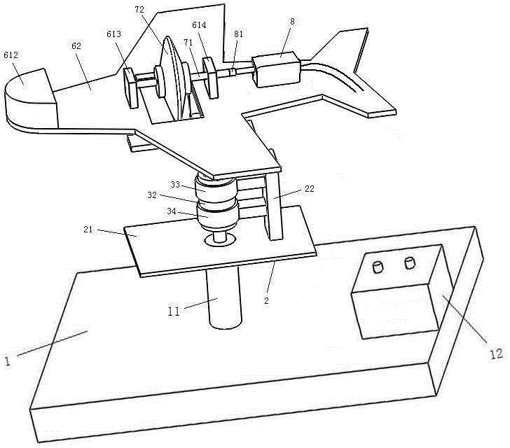
[0028] see figure 1 , figure 2 , image 3 , Figure 4 , Figure 5 , Figure 6 and Figure 7 , a gyro effect demonstrator of the invention includes a base 1 .

[0029] A vertical pole 11 is provided at the upper middle part of the base 1, and a battery 12 is provided at the right end.

[0030] A blind hole 111 is provided on the upper end surface of the vertical rod 11 , the inner bottom surface of the blind hole 111 is in a cone shape, and a brush holder 2 is provided on the upper end surface of the vertical rod 11 .

[0031] The brush holder 2 is composed of a bottom plate 21 and a non-conductive brush sleeve rod 22 with upper and lower non-conductive brush sleeves 221 , 222 .

[0032] A bottom plate hole 211 is provided in the middle of the bottom plate 21, and it is opposite to the blind hole 111 provided on the upper...


PUM


Abstract

The invention discloses a gyroscopic effect demonstrator. The gyroscopic effect demonstrator comprises a base. The gyroscopic effect demonstrator is characterized by further comprising a storage battery arranged on he base, a vertical rod, an electric brush carrier located on the vertical rod and formed by a bottom plate and a non-conductor electric brush sleeve rods equipped with upper and lower non-conductor electric brush sleeves, a rotating shaft crossed through a bottom plate hole on the bottom plate of the electric brush carrier and inserted to a blind hole of the vertical rod, a non-conductor metal electric brush ring base arranged with upper and lower metal electric brush rings on the rotating shaft, an operation handle fixed by a screw and an inside thread at the upper end face of the rotating shaft, and a U-shaped lower bracket, a reverse-U shaped upper bracket linked and rotated with two end parts of the U-shaped lower bracket through threads, and an airplane model body fixed on the reverse-U shaped upper bracket, wherein the lower end face of the airplane model body is provided with an upper airplane model plate arranged with a front support, a middle support and a back support, and the upper end face is provided with a lower airplane model plate arranged with a gyroscopic mini-sized direct current motor on an output shaft. Upper and lower electric brushes are arranged in the upper and lower non-conductor brush sleeves; upper and lower metal electric brush ring wiring terminals are drawn out by upper and lower metal electric brush rings. The gyroscopic effect demonstrator is applied to teach.

Description

technical field [0001] The invention relates to a teaching aid, in particular to a gyro effect demonstrator. Background technique [0002] Gyroscopes are a type of instrument used in navigation and navigation in the early days. With the development of science and technology, gyroscopes are also widely used in aerospace, military, and civilian equipment and other fields. The gyroscope can be used as a sensitive element in the automatic control system, that is, as a signal sensor. According to the needs, the gyroscope can provide accurate signals such as azimuth, level, position, speed and acceleration, and these signals are directly used to complete the attitude control and orbit of the vehicle in the guidance of missiles, satellite carriers or space exploration rockets. control. Therefore, it is very important to understand the basics of gyroscopes. Especially for students majoring in marine engineering and fishing boats, it is essential to learn gyroscopes. They all need ...

Claims


Application Information

Patent Timeline
Patent Type & Authority Applications(China)
IPC IPC(8): G09B23/18
CPCG09B23/10
Inventor 宋秋红徐少蓉杜凯董鹏飞王皓辉
Owner SHANGHAI OCEAN UNIV
Why Eureka
Try Eureka