Special cutter for machining small-diameter pore helical milling of composite material

A composite material, helical hole milling technology, applied in the direction of cutters, milling cutters, manufacturing tools, etc. for milling machines, can solve the problem of unsuitable helical milling for small diameter holes, not fully considering high-speed chatter, and improve tool processing. Difficulty in production and other problems, to achieve the effect of improving stiffness, improving chip removal performance, and improving anti-vibration

Inactive Publication Date: 2015-06-17
TIANJIN UNIV
View PDF11 Cites 8 Cited by
  • Summary
  • Abstract
  • Description
  • Claims
  • Application Information

AI Technical Summary

Problems solved by technology

[0005] The overall geometric design of the tool is not suitable for small-diameter holes in helical milling. When processing small-diameter holes in helical milling, it is necessary to fully consider the issues of chip removal, temperature and rigidity. The impact of chip removal is serious, and for small-diameter bars, it increases the difficulty of tool processing; secondly, because the tool diameter itself is required to be small, and the cutting speed required for processing carbon fiber composite materials is high, the required spindle speed will be Very high, this tool does not fully consider vibrations such as high-speed chatter during the helical milling process of the tool
Finally, this tool is designed for two materials: titanium alloy and carbon fiber composite material. The cutting performance of the two materials needs to be considered when designing the tool, and the effect of processing a single carbon fiber composite material is slightly worse.

Method used


Image

  • Special cutter for machining small-diameter pore helical milling of composite material
  • Special cutter for machining small-diameter pore helical milling of composite material
  • Special cutter for machining small-diameter pore helical milling of composite material

Examples


Embodiment Construction

[0013] The specific implementation manners of the present invention will be described in detail below in conjunction with the accompanying drawings.

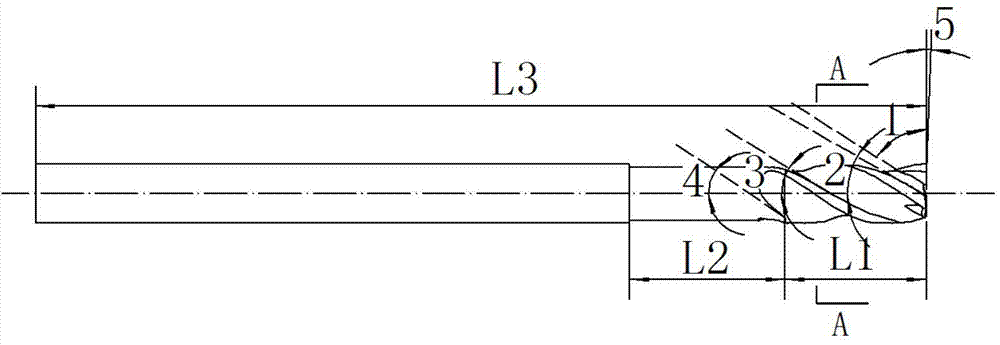
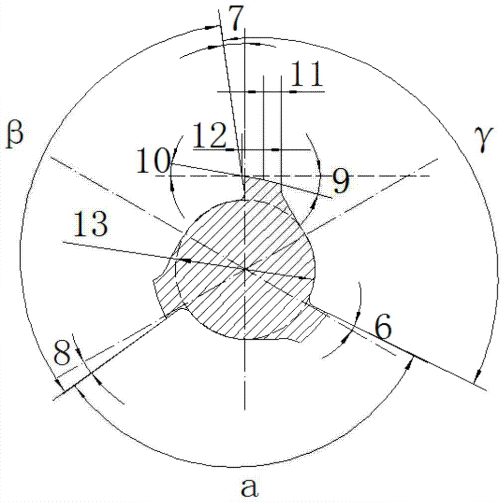
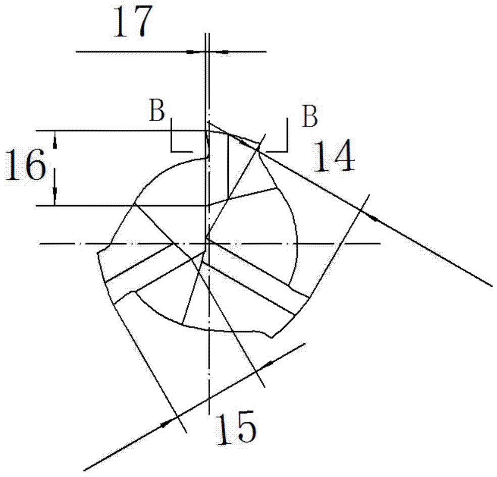
[0014] As shown in the accompanying drawings, the special cutting tool for processing small-diameter holes of composite materials for spiral milling of the present invention has first, second and third cutting edges on the cutting edge, and the included angles a and β between the three cutting edges , γ are not equal, wherein the angle a between the first cutting edge and the second cutting edge is 117°~119°, the angle β between the second cutting edge and the third cutting edge is 119°~121°, The included angle γ between the first cutting edge and the third cutting edge is 121°~123°, and the lengths of the three cutting edges are 14, 15, 16, and the length 14 of the first cutting edge is 1.5mm~1.6mm , the edge length 15 of the second cutting edge is 1.1 mm to 1.3 mm, the edge length 16 of the third cutting edge is 0.9 mm to 1.1 ...


PUM


Abstract

The invention discloses a special cutter for machining the small-diameter pore helical milling of a composite material. A first cutting edge, a second cutting edge and a third cutting edge are arranged on the cutting part of the cutter, and the included angles of the first cutting edge, the second cutting edge and the third cutting edge are different; the edge lengths of the three cutting edges are different; the back cutter faces of the three cutting edges are double back cutter faces with edge strips; the distances between the bottom edges of the three cutting edges and the center line of the cutter are different due to helical angles formed by the three cutting edges; the thickness of a milling cutter core is 70%-80% of the diameter of the cutter. The cutter comprehensively considers various problems of the geometrical shape of the cutter in helical milling machining of carbon fiber composite material small-diameter pores, the proportion of the thickness of the milling cutter core in the diameter of the cutter is improved, and the whole rigidity of the cutter is improved; by adopting the front angle of the cutter larger than an ordinary milling cutter, the cutting performance of the cutter for helical milling machining of the carbon fiber composite material is improved, the measures of reducing the back angle and the like are adopted, the strength of the small-diameter cutter cutting edge is improved, and the service life of the cutter is prolonged.

Description

technical field [0001] The invention relates to a special cutter for helical milling holes, in particular to a special cutter for helical milling holes of small-diameter composite materials. Background technique [0002] With the development of aerospace technology, the proportion of carbon fiber composite materials in aircraft components is increasing year by year. At present, in the assembly process of Chinese aircraft models, small-diameter holes account for a considerable proportion. However, the cutting process of carbon fiber composite materials is difficult, and it is easy to cause defects such as delamination, burrs, and tears. It is a typical difficult-to-machine material, especially for small holes on aircraft. [0003] Helical milling is a new type of hole-making technology. The helical milling process is formed by the joint action of three movements: spindle rotation, tool revolution around the center of the hole, and axial feed. However, the special tools for ...

Claims


Application Information

Patent Timeline
Patent Type & Authority Applications(China)
IPC IPC(8): B23C5/10
CPCB23C5/1081B23C2210/04B23C2210/0407B23C2210/0435B23C2210/0485B23C2210/202B23C2220/52B23C2222/28
Inventor 秦旭达田利成刘振旺李永行李皓赵庆于书宇张笑宇
Owner TIANJIN UNIV
Why Eureka
Try Eureka