Automobile air rotary compression energy storage type braking system

A technology of rotary compression and braking system, which is applied to vehicle parts, brakes, transportation and packaging, etc. It can solve the problems of wearing out brake pads, hindering the operation of the transmission, and energy loss, so as to achieve the effect of increasing the braking torque

Inactive Publication Date: 2015-06-17
CHONGQING UNIV
View PDF6 Cites 3 Cited by
  • Summary
  • Abstract
  • Description
  • Claims
  • Application Information

AI Technical Summary

Problems solved by technology

However, the disadvantage of such a system is that it consumes the power of the engine. On the one hand, the energy is inevitably dissipated on frictional heat, which consumes the brake pads. On the other hand, the high-pressure gas cannot be recovered and stored in the gas storage tank after braking. , waste and hot gases are discharged into the atmosphere, resulting in energy loss
But the weak point of this scheme is that the compression mechanism position setting is unreasonable, can not brake effectively, can hinder the work of speed changer, and can reduce the service life of drive shaft; Complexity can limit the design of the car body
The structure of this scheme is relatively clear and simple. However, the energy storage function has a slow response and is limited to long-term taxiing and other working conditions where the braking force demand is not large. Overall, the economic performance is poor.

Method used


Image

  • Automobile air rotary compression energy storage type braking system
  • Automobile air rotary compression energy storage type braking system

Examples


Embodiment Construction

[0026] The preferred embodiments of the present invention will be described in detail below with reference to the accompanying drawings.

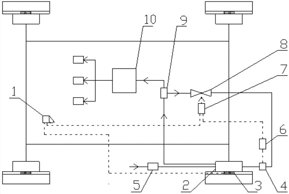
[0027] figure 1 It is a schematic diagram of the system structure of the present invention. As shown in the figure, the system includes: a sliding vane air compression device 2, a pedal and an angular displacement sensor 1, an electromagnetic clutch 3, a pressure feedback transmitter 6, a voltage comparator 7, Solenoid valve 8, low pressure air inlet 5, high pressure air inlet 4, buffer tank 9, gas storage tank 10, and connecting gas pipelines and signal transmission lines.

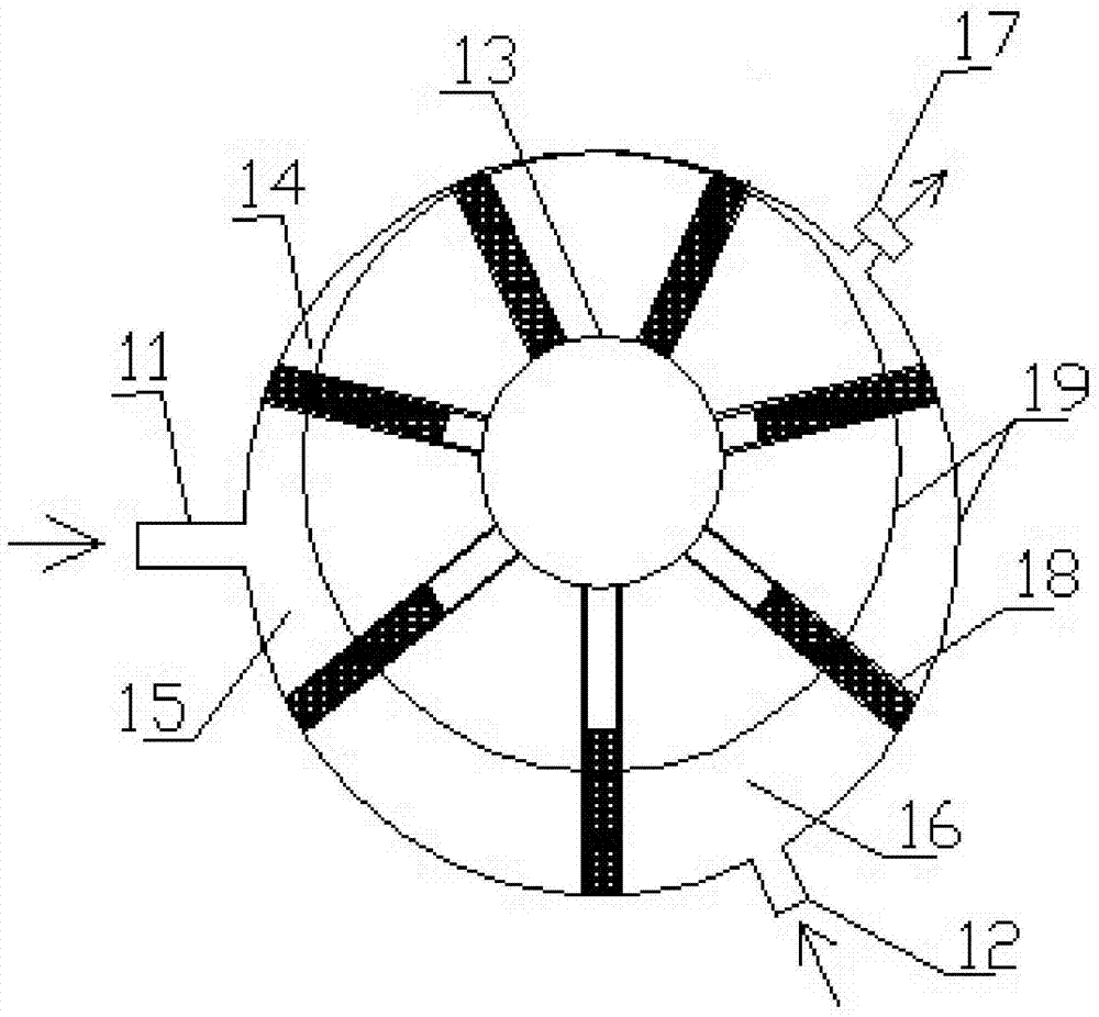
[0028] For the gas pipeline connection circuit, the gas storage tank 1 is connected to the buffer tank 9 through the one-way valve, the buffer tank 9 is connected to the air outlet 17 of the sliding-vane air compression device 2 through the one-way valve, and the sliding-vane air compression device 2 is connected to the electromagnetic Clutch 3, the sliding vane air c...


PUM


Abstract

The invention relates to an automobile air rotary compression energy storage type braking system and belongs to the technical field of automobile control. The system mainly comprises a sliding vane type air compression device, a pedal and angle displacement inductor, an electromagnetic clutch, a pressure feedback transducer, a voltage comparator, an electromagnetic valve, a low-pressure air inflow device, a high-pressure air inflow device, a buffer box and an air storage tank. By the adoption of the system, force is acquired from rotation of an axle in the automobile braking process, the sliding vane type air compression device installed in the position of a brake disc is driven, air compression energy storage is conducted, power is adjusted and controlled by adjusting the initial pressure of air before the air is compressed, high-intensity air compression is achieved, and the large counter torque is output to stop an automobile from moving forwards continuously. By the adoption of the automobile air rotary compression energy storage type braking system, energy can be recycled and stored immediately under the common braking condition, braking operation is conducted on the brake disc through small-size high-intensity rotary air compression design, the system accords with a traditional braking operation habit, and the safety performance and the economic performance of the air rotary compression energy storage type braking system are improved.

Description

technical field [0001] The invention belongs to the technical field of automobile control, and relates to an automobile air rotary compression energy storage brake system. Background technique [0002] At present, many automobiles and passenger cars use pneumatic brakes. The advantages of air brake are large braking torque, short pedal stroke, easy operation and reliable use. The function of the air compressor next to the car engine is to generate compressed air, which is the power source. The air compressor is driven by the power of the engine, and the compressed gas makes the wheels brake. The driver only needs to control the stroke of the pedal according to different braking intensity requirements, release different degrees of compressed air, and then adjust the gas pressure to obtain the required braking force. However, the disadvantage of such a system is that it consumes the power of the engine. On the one hand, it inevitably dissipates energy in frictional heat, wh...

Claims


Application Information

Patent Timeline
Patent Type & Authority Applications(China)
IPC IPC(8): B60T13/68
CPCB60T13/683
Inventor 刘永刚黄雷王川航文保林刘长春秦大同
Owner CHONGQING UNIV
Why Eureka
Try Eureka