A dual power supply automatic transfer switch appliance
An automatic transfer switch and dual power supply technology, which is applied in relays, emergency power supply arrangements, circuits, etc., can solve the problems of unsatisfactory mechanical interlock reliability, failure to meet the use requirements, slow conversion speed, etc., and achieve obvious power saving effects. Good dustproof effect and close power factor
- Summary
- Abstract
- Description
- Claims
- Application Information
AI Technical Summary
Problems solved by technology
Method used
Image
Examples
Embodiment 1
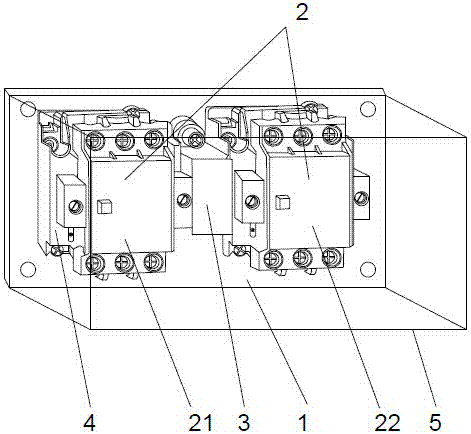
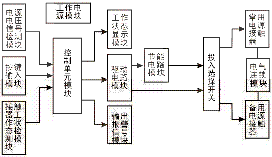
[0041] Example 1: see Figure 1 ~ Figure 2 , a dual-power automatic transfer switch electrical appliance, including a base 1, two AC contactors 2 arranged on the base 1 as a normal power switch and a backup power switch respectively, and being arranged between the two AC contactors to avoid The mechanical interlock device 3 for the two AC contactors 2 to be closed at the same time, and the controller for controlling the operation of the two AC contactors 2; wherein, the AC contactor 2 located at the switch end of the common power supply is defined as the common contactor 21, which is located at The AC contactor 2 at the switch end of the standby power supply is defined as a standby contactor 22; it is characterized in that: the controller includes a control circuit, and the control circuit includes a working power supply module for supplying power to the system circuit, as a control unit module for central data processing, respectively connected with The power supply voltage s...
Embodiment 2
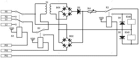
[0050] Example 2: see figure 2, this embodiment is basically the same as Embodiment 1, except that: the instantaneous high-voltage starting circuit includes a high-voltage rectifier bridge BG2', and a starting relay K1' with double sets of normally open contacts that controls the switching of the instantaneous high-voltage starting circuit; The low-voltage holding circuit includes a step-down transformer T1'; wherein, the common end of the starting relay K1' and the input end of the step-down transformer T1' are connected to the common end of the power selection relay K3', and the normally open output end of the starting relay K1' and The output terminals of the step-down transformer T1' are all connected to the input terminals of the high voltage rectifier bridge BG2'; the output terminals of the high voltage rectifier bridge BG2' are connected to the common terminal of the input selection switch K2'. The input selection switch K2' is a normally open contact and a normally...
PUM
 Abstract
Description
Claims
Application Information
 - R&D
- Intellectual Property
- Life Sciences
- Materials
- Tech Scout
- Unparalleled Data Quality
- Higher Quality Content
- 60% Fewer Hallucinations
Browse by: Latest US Patents, China's latest patents, Technical Efficacy Thesaurus, Application Domain, Technology Topic, Popular Technical Reports.
© 2025 PatSnap. All rights reserved.Legal|Privacy policy|Modern Slavery Act Transparency Statement|Sitemap|About US| Contact US: help@patsnap.com


