
Radiator and cooling system

A radiator and technology to dissipate heat, applied in circuit thermal devices, semiconductor devices, electric solid devices, etc., can solve the problem of difficult to control the filling amount of thermally conductive materials, and achieve the problem of difficult to control the filling amount of thermally conductive materials, simple structure, and thermal conductivity efficiency. high effect

Active Publication Date: 2015-06-17
HUAWEI TECH CO LTD
View PDF6 Cites 15 Cited by
  • Summary
  • Abstract
  • Description
  • Claims
  • Application Information

AI Technical Summary

Problems solved by technology

[0004] The embodiment of the present invention provides a heat sink, which can solve the problem in the prior art that the filling amount of heat-conducting material between the heat sink and the chip is difficult to control

Method used


Image

  • Radiator and cooling system
  • Radiator and cooling system
  • Radiator and cooling system

Examples


Embodiment Construction

[0023] The following will clearly and completely describe the technical solutions in the embodiments of the present invention with reference to the accompanying drawings in the embodiments of the present invention. Obviously, the described embodiments are only some, not all, embodiments of the present invention. Based on the embodiments of the present invention, all other embodiments obtained by persons of ordinary skill in the art without making creative efforts belong to the protection scope of the present invention.

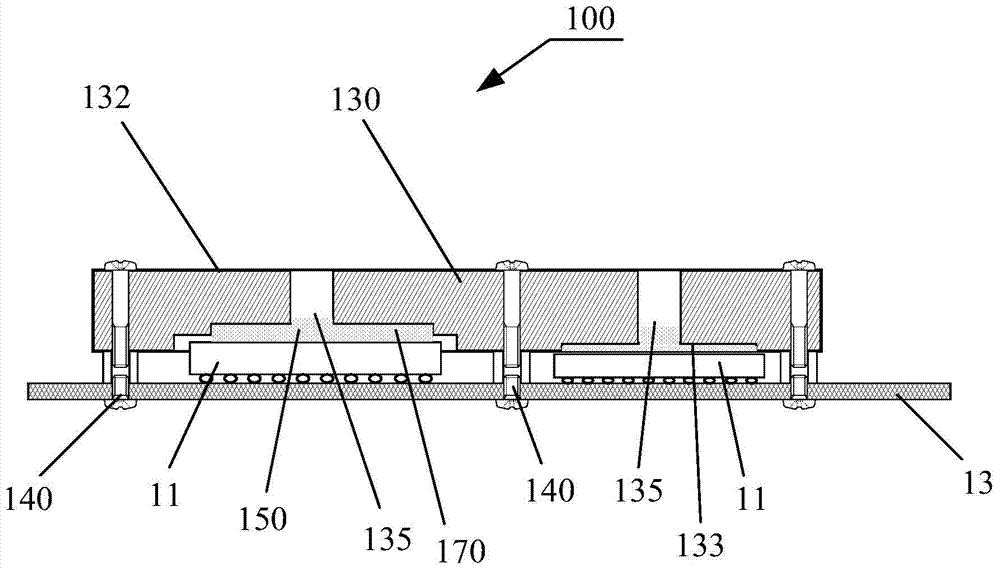
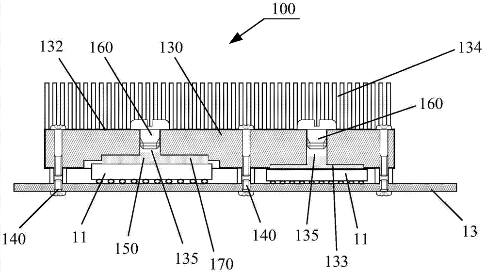
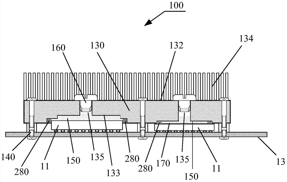
[0024] see figure 1 , is a cross-sectional view of a heat sink 100 provided by an embodiment of the present invention. The heat sink 100 is used to dissipate heat for the electronic components 11 to be dissipated. The electronic components 11 are mounted on the circuit board 13 and electrically connected to the circuit board 13 . Wherein, the circuit board 13 and the heat sink 100 constitute a heat dissipation system.

[0025] The circuit board 13 may be a p...


PUM


Abstract

The present invention discloses a heat sink, including a heat sink body and a filling material. A through hole is disposed in a position, corresponding to a to-be-cooled electronic element, on the heat sink body. The to-be-cooled electronic element is mounted on a circuit board and located between the circuit board and the heat sink body. There is a gap between the to-be-cooled electronic element and the heat sink body. The gap is connected to the through hole. The filling material is injected into the through hole and fills the gap. The present invention further discloses a heat dissipation system having the heat sink. The heat sink resolves problems in the prior art that, a heat sink has low thermal conduction efficiency and it is difficult to control a filling volume of a thermally conductive material in a gap between a heat sink and a chip.

Description

technical field [0001] The invention relates to computer and microelectronic technology, in particular to a radiator and a cooling system. Background technique [0002] With the development of microelectronics technology, the integration of electronic chips is increasing day by day, and the power consumption of each electronic chip is also increasing. Therefore, electronic chips, such as the central processing unit (CPU) in computers, The heat flux density is also getting higher and higher. In practical applications, in addition to the need to conduct heat away from the electronic chip, in a single-board system containing multiple electronic chips, it is also necessary to ensure that the temperature on the single board can be evenly distributed to avoid damage due to heat concentration at one point. Electronic chip or single board. Therefore, in practical engineering applications, heat dissipation devices are widely installed on or close to electronic chips to conduct heat...

Claims


Application Information

Patent Timeline
Patent Type & Authority Applications(China)
IPC IPC(8): H01L23/42H01L23/367H05K7/20
CPCH01L23/3675H01L23/4006H01L23/42H01L2224/16225H01L2224/73253H01L2924/0002H05K1/0203H01L2924/00
Inventor 张俊王永生曹璐
Owner HUAWEI TECH CO LTD
Learn More