A reversible end assembly applied to a wafer transfer robot

A robot and component technology, applied in the directions of manipulators, joints, chucks, etc., can solve the problem of air tightness of the rotary cylinder accuracy, and achieve the effect of improving the turning accuracy and speed, simplifying the structure, and improving the transmission accuracy.

Active Publication Date: 2016-08-24
BEIJING UNIV OF TECH
View PDF6 Cites 3 Cited by
  • Summary
  • Abstract
  • Description
  • Claims
  • Application Information

AI Technical Summary

Problems solved by technology

However, the design of the additional air circuit is added to the rotary cylinder, and there are also problems of precision and air tightness in the rotary cylinder

Method used


Image

  • A reversible end assembly applied to a wafer transfer robot
  • A reversible end assembly applied to a wafer transfer robot
  • A reversible end assembly applied to a wafer transfer robot

Examples


Embodiment Construction

[0015] Specific embodiments of the present invention will be described in detail below in conjunction with specific drawings.

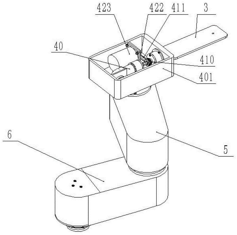
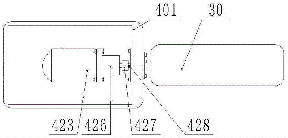
[0016] like Figure 1-3 As shown, the reversible terminal assembly includes a wrist housing 401 , a servo motor 423 , a motor pulley 422 , a steel belt 411 , a rotary mechanism 40 , and a vacuum suction terminal 3 . The robot wrist housing 401 is connected to one end of the forearm 5, the servo motor 423 is installed in the wrist housing 401, the motor pulley 422 is installed on the output shaft of the servo motor, and the steel belt 411 is connected between the motor pulley 422 and the rotary mechanism pulley 410. Between them, the rotary mechanism pulley 410 is fixed on the rotary mechanism 40, one end (left end) of the rotary mechanism 40 is fixed inside the wrist housing 401, and the other end (right end) is connected to the vacuum adsorption terminal 3, wherein the left end of the rotary mechanism 40 is connected to the vacuum pipe joint ( not s...


PUM


Abstract

Provided is a reversible tail end assembly applied to a wafer conveying robot. A wrist shell of the robot is connected with one end of a small arm, a servo motor is installed in the wrist shell, a motor belt wheel is installed on an output shaft of the servo motor, a steel strip is connected between the motor belt wheel and a swing mechanism belt wheel, the swing mechanism belt wheel is fixed on a swing mechanism, one end of the swing mechanism is fixed in the wrist shell, the other end of the swing mechanism is connected with a vacuum adsorption tail end, and the left end of the swing mechanism is connected with a vacuum air tube joint. In other embodiments, the servo motor can also be replaced with other motors. When a wafer is adsorbed, vacuums are firstly generated in a fixed bent tube and a fixed outer tube, a vacuum can also be generated in a rotating inner tube while the rotating inner tube rotates, vacuum pressure is generated in a hollow duct of the vacuum adsorption tail end and an inner duct of a vacuum tail end connecting shaft, the wafer is adsorbed by means of a difference between internal pressure and external pressure, and vacuum pressure is generated in an inner duct of the swing mechanism while the swing mechanism rotates. Line winding is prevented, and coaxial design of a reversal action and a vacuum generation action is achieved.

Description

technical field [0001] The invention relates to a reversible end assembly applied to a wafer transfer robot, and belongs to the technical field of wafer robot design. Background technique [0002] During the wafer handling process, various working conditions require the flipping of the wafer during the handling process. Such as the wafer transfer robot invented by Kang Renke of Dalian University of Technology, patent number: ZL200420113013.1, publication number: CN2762970Y, authorized publication date: March 8, 2006. Its end turning mechanism is driven by a rotary cylinder, and a rotating air circuit assembly is also designed to realize vacuum air transmission and at the same time realize the turning of the end. However, the design of the additional air circuit is added to the rotary cylinder, and there are also problems of precision and air tightness in the rotary cylinder. Using motor drive, the layout of the control circuit is relatively simple, and the motor drive is m...

Claims


Application Information

Patent Timeline
Patent Type & Authority Patents(China)
IPC IPC(8): B25J11/00B25J17/00B25J15/06
Inventor 刘志峰谷光伟
Owner BEIJING UNIV OF TECH
Why Eureka
Try Eureka