UVLED curing light source, printing equipment using the light source, and driving control method thereof
A technology for driving control circuits and light sources, applied in light sources, electric light sources, lighting devices, etc., can solve the problems of inconsistent optical energy density and non-adjustable optical energy density in each local area of the light-emitting window, optimize curing effect and reduce energy waste. Loss, the effect of prolonging the life of the light source
- Summary
- Abstract
- Description
- Claims
- Application Information
AI Technical Summary
Problems solved by technology
Method used
Image

Examples
Embodiment 1
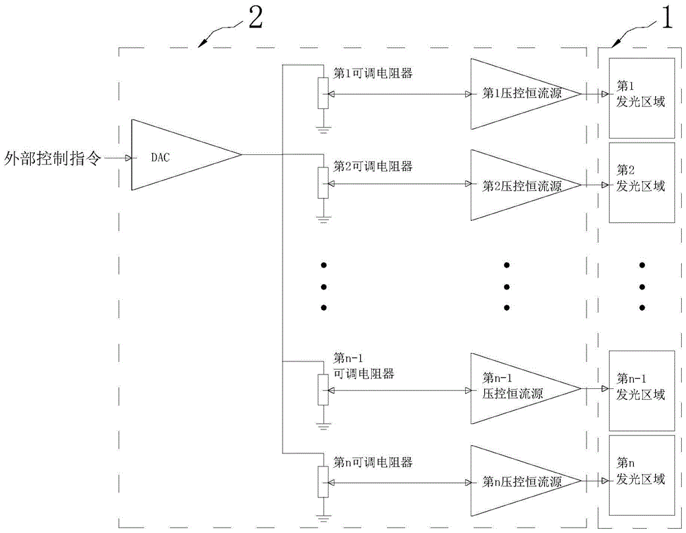
[0025] like figure 1 As shown, the UVLED curing light source of Embodiment 1 of the present invention includes a rectangular light emitting window 1 , a UVLED lamp array and a drive control circuit module 2 .
[0026] The above-mentioned UVLED lamp array is covered with a rectangular light-emitting window 1, and the UVLED lamps forming the UVLED light array emit ultraviolet rays through the rectangular light-emitting window 1; and the rectangular light-emitting window 1 divides two or more light-emitting areas arranged along the long side of the rectangular light-emitting window 1 , including the 1st to nth light-emitting regions, where n is a positive integer greater than or equal to 2.
[0027] The drive control circuit module 2 is provided with a control signal input terminal for receiving external setting instructions, a power supply output terminal corresponding to each light-emitting area of the rectangular light-emitting window 1, a digital-to-analog signal converter,...
Embodiment 2
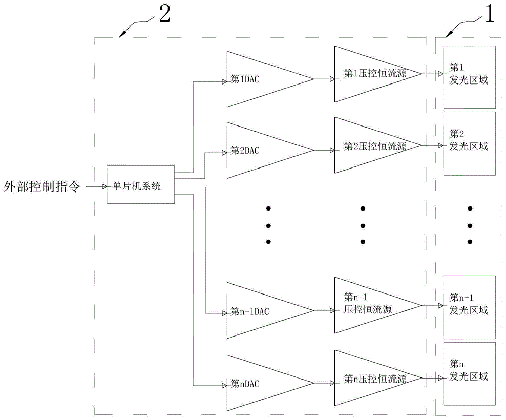
[0030] like figure 2 As shown, the UVLED curing light source of the second embodiment of the present invention is basically the same as the first embodiment, and their difference lies in the implementation of the drive control circuit module 2. Specifically: the drive control circuit module 2 of the second embodiment is provided with a receiving The control signal input terminal of the external control command, each light-emitting area corresponding to the rectangular light-emitting window 1 is provided with a power supply output terminal, the output signal is controlled by the single-chip microcomputer system of the external control command, and a set of digital-to-analog signal conversion is provided corresponding to each power supply output terminal device and a voltage-controlled constant current source. The single-chip microcomputer system has a signal output terminal corresponding to each group of digital-analog signal converters and voltage-controlled constant-current so...
Embodiment 3
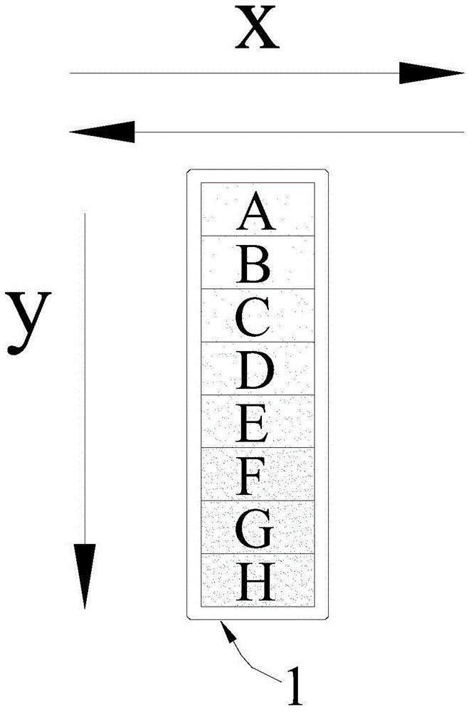
[0032] like image 3 and Figure 4 As shown, Embodiment 3 of the present invention is a preferred implementation of UVLED curing light source, which can adopt the structure of Embodiment 1 or Embodiment 2. The difference is that in Embodiment 3, the width of the rectangular light-emitting window 1 is 2cm , with a length of 8 cm, the rectangular light-emitting window 1 is provided with eight rectangular light-emitting areas of the same shape and size from A to H in sequence according to the long side direction, and each rectangular light-emitting area has a width of 2 cm and a length of 1 cm. The power of the UVLED lamps in the eight rectangular light-emitting areas obtained by the drive control circuit module satisfies: W A =W B C D E F =W G =W H , so as to adjust the light energy density of the eight light-emitting regions accordingly. In the figure, the y direction represents the one-way moving direction of the target inkjet medium, and the x direction represents the ba...
PUM
 Abstract
Description
Claims
Application Information
 - R&D
- Intellectual Property
- Life Sciences
- Materials
- Tech Scout
- Unparalleled Data Quality
- Higher Quality Content
- 60% Fewer Hallucinations
Browse by: Latest US Patents, China's latest patents, Technical Efficacy Thesaurus, Application Domain, Technology Topic, Popular Technical Reports.
© 2025 PatSnap. All rights reserved.Legal|Privacy policy|Modern Slavery Act Transparency Statement|Sitemap|About US| Contact US: help@patsnap.com