Diffracted wave imaging method and device based on L0 semi-norm

An imaging method and diffraction wave technology, applied in the field of seismic exploration, can solve the problems of inability to take into account the signal-to-noise ratio of seismic data, etc., and achieve the effects of enhancing the signal-to-noise ratio of diffraction wave imaging, easy identification, and improving the signal-to-noise ratio of data

Active Publication Date: 2015-06-24
INST OF GEOLOGY & GEOPHYSICS CHINESE ACAD OF SCI
View PDF3 Cites 9 Cited by
  • Summary
  • Abstract
  • Description
  • Claims
  • Application Information

AI Technical Summary

Problems solved by technology

[0006] The purpose of the present invention is to provide a diffraction wave imaging method based on the L0 semi-norm, which solves the problem that the existing diffraction wave imaging technology can

Method used


Image

  • Diffracted wave imaging method and device based on L0 semi-norm
  • Diffracted wave imaging method and device based on L0 semi-norm
  • Diffracted wave imaging method and device based on L0 semi-norm

Examples


Embodiment Construction

[0019] The present invention will be described in detail below in conjunction with the accompanying drawings and specific embodiments.

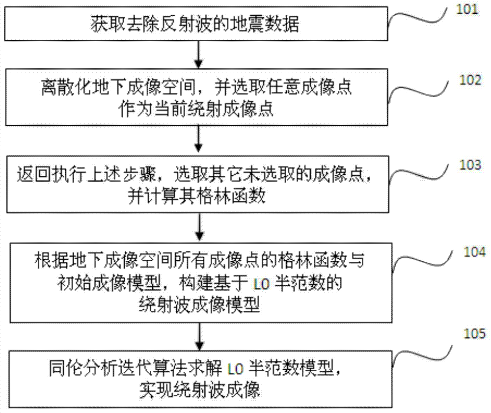
[0020] Such as figure 1 As shown, a kind of diffracted wave imaging method based on the L0 semi-norm that the present invention proposes comprises the following steps:

[0021] Step 101: Obtain a seismic data from which reflected waves have been removed as input data; the corresponding seismic data can be pre-stack shot seismic data or post-stack seismic data, and the method of removing reflected waves uses a plane wave damage filtering method;

[0022] Step 102: Discretize the underground imaging space, select any imaging point as the current diffraction imaging point, and calculate the above-mentioned arbitrary diffraction imaging according to the relationship between the shot point and the receiver point in the input seismic data and the given velocity model Green's function of the point;

[0023] Step 103: cyclically execute other imagi...


PUM


Abstract

The invention discloses a diffracted wave imaging method based on the L0 semi-norm. The method comprises the steps that seismic data with no reflected waves are obtained to be used as input data; discretization is carried out on underground imaging space, any imaging point is selected as the current diffracted imaging point, and a green function of any diffracted imaging point is calculated according to a given speed model and the relation between short points and wave detection points in the input seismic data; other imaging points which are not selected are executed in a loop mode, and other corresponding green functions are calculated until the green functions of all the imaging points in the underground imaging space are obtained; a diffracted wave imaging model based on the L0 semi-norm is built; the homotopy analysis iterative algorithm is used for solving the model, and a diffracted wave imaging result is obtained. The invention further discloses a diffracted wave imaging device based on the L0 semi-norm. By means of the diffracted wave imaging method and device based on the L0 semi-norm, the seismic data imaging resolution ratio can be improved, the diffracted wave imaging signal to noise ratio is increased, and therefore a small-scale geological unit related to reservoir space connectivity can be recognized more easily.

Description

technical field [0001] The invention belongs to the field of exploration seismic technology, and relates to a diffraction wave imaging method based on the L0 half norm, and also relates to a diffraction wave imaging device based on the L0 half norm. Background technique [0002] In the process of exploration and development of oil and gas resources, effective identification of structural and lithological anomalies, such as karst caves, fractures, formation pinch-outs, and weathering crusts, is crucial to reservoir understanding. The above-mentioned small-scale geological bodies are usually smaller or much smaller than the wavelength of the seismic wavelet in terms of spatial distribution, so they exist in the form of diffracted waves in seismic data. During field operations, the seismic signals received by the geophone include reflected waves and diffracted waves, and the reflected wave imaging condition assumes an infinite smooth interface, so generally it can only reflect ...

Claims


Application Information

Patent Timeline
IPC IPC(8): G01V1/28
Inventor 于彩霞王彦飞
Owner INST OF GEOLOGY & GEOPHYSICS CHINESE ACAD OF SCI
Why Eureka
Try Eureka