Planar-broadband dual-polarization base station antenna

A base station antenna and dual-polarization technology, which is applied in the field of planar broadband dual-polarization base station antenna and broadband dual-polarization The effect of area and simplified structure

Inactive Publication Date: 2015-06-24
XIDIAN UNIV
View PDF7 Cites 43 Cited by
  • Summary
  • Abstract
  • Description
  • Claims
  • Application Information

AI Technical Summary

Problems solved by technology

[0004] The purpose of the present invention is to overcome the defects of the above-mentioned existing base station antennas, and propose a planar broadband dual-polarization base station antenna, which is used to solve the complex structure and Difficult to integrate with other devices

Method used


Image

  • Planar-broadband dual-polarization base station antenna
  • Planar-broadband dual-polarization base station antenna
  • Planar-broadband dual-polarization base station antenna

Examples


Embodiment 1

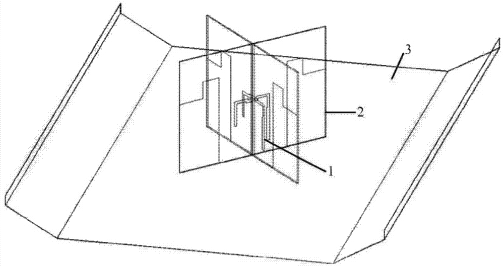
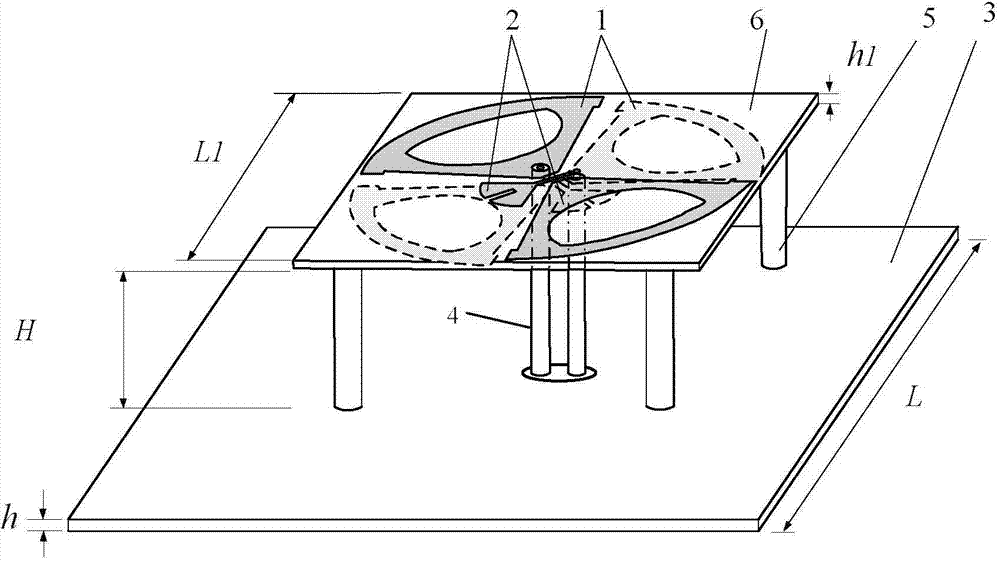
[0025] refer to figure 2 , the present invention includes a radiation oscillator 1, a feeding balun 2, a reflector 3, a coaxial line 4, a support column 5, and a dielectric material plate 6; the radiation oscillator 1 and the feeding balun 2 are plated with metal copper, and the radiation oscillator 1 The ±45° dual-polarized planar oscillator is adopted, and the feed balun 2 adopts the ±45° planar feed balun; the reflector 3 is made of a square aluminum plate, or other metal materials can be used to form one-way reflection. The length L is 140mm, the thickness h is 1mm, and a through hole is provided at the center for the coaxial line to pass through; the support column 5 is made of plastic material, or other non-metallic materials can be used to avoid affecting the antenna radiation performance; the dielectric material plate 6. The FR-4 material with a dielectric constant of 4.4 is used. The surface shape is a square with a side length L1 of 52 mm and a thickness h1 of 1 mm;...

Embodiment 2

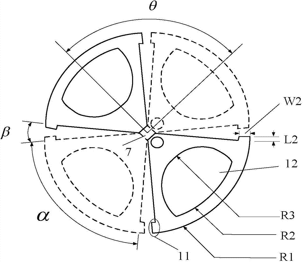
[0029]Embodiment 2 has the same structure as Embodiment 1, and only the following parameters are modified: the radii of the two sections of circular arcs forming the similar circular hole 12 are respectively R2=19mm, R3=9mm, and the 3 side lengths of the reflecting plate L=130mm, The length L3 of the rectangular slit is 3 mm, the width W is 0.5 mm, the central angle γ of the fan-shaped stub 21 is 65°, and the radius R is 5 mm.

Embodiment 3

[0031] Embodiment 3 has the same structure as Embodiment 1, and only the following parameters are modified: the radii of the two sections of arc lines forming the similar circular hole 12 are respectively R2=23mm, R3=11mm, and the reflector 3 side lengths L=150mm, The length of the rectangular slit L3=5mm, the wide band W=1.5mm, the central angle γ of the fan-shaped stub 21=85°, and the radius R=7mm.

[0032] Advantage of the present invention can be further illustrated by the simulation result of embodiment 1:

[0033] 1. Simulation content

[0034] The above-mentioned embodiment 1 is simulated by using the simulation software HFSS. The voltage standing wave ratio results are as follows Figure 5 Shown; the oscillator port isolation results are as follows Figure 6 As shown; when the +45° oscillator is fed by a single port, the results of the far-field radiation pattern at the three frequency points of 1.8GHz, 2.2GHz, and 2.6GHz are as follows Figure 7 Table 1 shows the ...


PUM


Abstract

The invention discloses a planar-broadband dual-polarization base station antenna and belongs to the field of mobile communication base station antennae. The planar-broadband dual-polarization base station antenna mainly solves the problems that an existing base station antenna is complex in structure and has difficulty in being integrated with other devices. The planar-broadband dual-polarization base station antenna comprises radiation oscillators (1), feed baluns (2), a baffle board (3), coaxial cables (4), supporting columns (5) and a dielectric material plate (6). The radiation oscillators (1) are dual-polarization planar oscillators at +/-45 degrees, and the feed baluns (2) are planar feed baluns at +/-45 degrees. The radiation oscillator at -45 degrees and the feed balun at +45 degrees are printed on the upper surface of the dielectric material plate (6), and the radiation oscillator at +45 degrees and the feed balun at -45 degrees are printed on the lower surface of the dielectric material plate (6). The dielectric material plate (6) is fixed to the square baffle board (3) through the supporting columns (5). According to the planar-broadband dual-polarization base station antenna, planarization of the radiation oscillators and the feed baluns are achieved, meanwhile, the structure of the baffle board is simplified, and a stable directional diagram characteristic can be obtained in broadband.

Description

technical field [0001] The invention belongs to the technical field of antennas, and relates to a broadband dual-polarization base station antenna, in particular to a planar broadband dual-polarization base station antenna by printing a radiation oscillator and a feed balun on a dielectric board, which can be applied to mobile In the field of communication base station antennas. Background technique [0002] Mobile communication technology has brought fast information communication to human beings, and at the same time, the increase in demand has also promoted the vigorous development of mobile communication technology. The first-generation analog mobile communication system gradually faded out of our field of vision, the second-generation digital mobile communication system is in the ascendant, and then the third-generation broadband mobile communication system is being built worldwide. The fourth-generation mobile communication technology is being tested and Construction ...

Claims


Application Information

Patent Timeline
Patent Type & Authority Applications(China)
IPC IPC(8): H01Q1/38H01Q1/36H01Q1/52H01Q15/18
Inventor 刘英王玖章玉涛龚书喜
Owner XIDIAN UNIV
Why Eureka
Try Eureka