Eureka AIR delivers breakthrough ideas for toughest innovation challenges, trusted by R&D personnel around the world.

Optical multiplexer and emitting light device

An optical multiplexer and light-emitting technology, which is applied in the field of optical communication, can solve the problems of difficult OMUX production, large packaging loss, and complicated manufacturing process.

Active Publication Date: 2015-06-24
HUAWEI TECH CO LTD
View PDF6 Cites 8 Cited by
  • Summary
  • Abstract
  • Description
  • Claims
  • Application Information

AI Technical Summary

Problems solved by technology

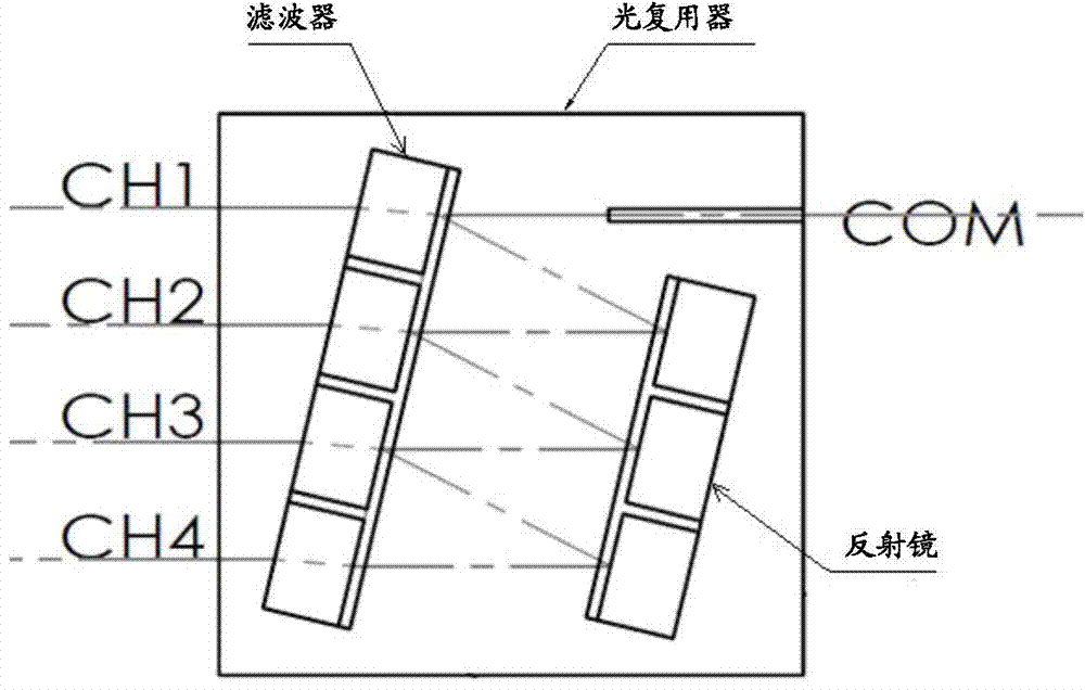
The disadvantages of this solution are: multiple TFFs (Thin-Film Filters, thin-film filters) are required, the optical path between each channel is unbalanced, and the output light power varies greatly; it is difficult to insert other optical components inside the OMUX, and the device length is long; multiple WDM TFF cost is high; the assembly process is complicated, and OMUX production is difficult; it is not suitable for dense wavelength division multiplexing DWDM
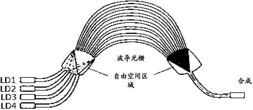
The disadvantage of this solution is that the use of AWG leads to large packaging loss. At the same time, AWG is difficult to manufacture, and AWG usually needs to work at a constant temperature, and temperature control is required;
[0006] It can be seen that the current optical multiplexers have disadvantages such as large packaging volume or large packaging loss, complicated manufacturing process, etc.

Method used


Image

  • Optical multiplexer and emitting light device
  • Optical multiplexer and emitting light device
  • Optical multiplexer and emitting light device

Examples


Embodiment 1

[0070] Take 4 beams of light as an example to illustrate. In this embodiment, firstly, 2 PBC light combiners are used as the first-level light combining components to combine 4 beams of light into 2 beams, and then a beam splitting prism light combiner is used as the The second-stage light-combining component further combines the two beams of light into one beam of light and outputs it.

[0071] Such as Figure 6 As shown, after the light emitted by LD1 is collimated by the collimating lens (Lens), and then rotated 90 degrees by the half-wave plate whose optical axis is at an angle of 45 degrees to the polarization direction of the incident light, its polarization direction is exactly the same as that of the light emitted by LD2 The directions are perpendicular to each other, and after turning the light path through the reflector, it can combine with the light emitted by LD2 through PBC1 to form a beam of light, and then incident on a beam splitting prism placed at an angle of...

Embodiment 2

[0073] Take 4 beams of light as an example to illustrate. In this embodiment, firstly, 2 beam splitting prism light combiners are used as the first-level light combining components to combine 4 beams of light into 2 beams, and then a PBC light combiner is used as the The second-stage light-combining component further combines the two beams of light into one beam of light and outputs it.

[0074] Such as Figure 7 As shown, the light emitted by LD1 is collimated by the collimating lens, then passes through the reflector to turn the light path, and is reflected by 50% of the energy by the 3dB dichroic prism, and then combined with the light emitted by LD2 and transmitted by 50% of the energy by the 3dB dichroic prism Light; similarly, the light emitted by LD4 is collimated by the collimating lens, then passes through the mirror to turn the light path, and is reflected by 50% of the energy by the 3dB beam splitting prism, and synthesized with the light emitted by LD3 and transmit...


PUM


Abstract

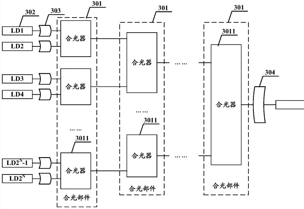
The present invention discloses an optical multiplexer and a transmitter optical subassembly, and relates to the field of optics communications. A light-combining part is formed by using at least one light combiner that can combine two beams of light into one beam of light, and at least two levels of light-combining parts are used to constitute an optical multiplexer, so that 2 N beams of light are combined into one beam by using N level of light-combining parts, thereby reducing a package size and packaging loss, and reducing the complexity of a manufacturing process.

Description

technical field [0001] The invention relates to the field of optical communication, in particular to an optical multiplexer and an optical emitting device. Background technique [0002] At present, 40G QSFP+ (Quad Small Form-factor Pluggable Plus, four-channel small pluggable) or CFP2 (100G Form Factor Pluggable2, the second generation of gigabit pluggable), CFP4 optical modules need to transmit light from 4 lasers from PID TOSA (Photonic Integrated Device Transmitter Optical Subassembly, integrated emitting optical device) that 4 ports are collected and output from 1 port. This type of device requires small size and high density, especially for 100G CFP2 / CFP4 or 400G modules, because the light source needs to meet Lane WDM (LAN Emulation Wavelength-Division Multiplexer, LAN Emulation Wavelength-Division Multiplexer) or even DWDM (Dense Wavelength-Division Multiplexer, dense wavelength division multiplexing) standard, the wavelength interval is small, and it is especially d...

Claims


Application Information

Patent Timeline
IPC IPC(8): H04J14/02
CPCG02B6/2713G02B6/2746G02B6/2773G02F1/093H04J14/00G02B27/14G02B27/126G02B27/283G02B6/2938H04J14/08G02B6/272H04J14/02H04J14/06
Inventor 张学明宛政文
Owner HUAWEI TECH CO LTD
Why Eureka
Eureka Blog
Learn More