Variable angle supersonic vibration auxiliary grinding device for precision and ultra-precision machining

A technology of ultra-precision machining and ultrasonic vibration, which is applied in metal processing equipment, parts of grinding machine tools, grinding/polishing equipment, etc., can solve the problem of inability to adjust the direction of ultrasonic vibration and the angle of the grinding wheel, and achieve low cost and simple operation Effect

Inactive Publication Date: 2015-07-01
UNIV OF SHANGHAI FOR SCI & TECH
View PDF5 Cites 5 Cited by
  • Summary
  • Abstract
  • Description
  • Claims
  • Application Information

AI Technical Summary

Problems solved by technology

[0005] At present, the ultrasonic vibration device generally used applies ultrasonic vibration in the axial direction or tangential direction of the grinding wheel, and the angle between the direction of ultrasonic vibration and the grinding wheel cannot be adjusted.

Method used


Image

  • Variable angle supersonic vibration auxiliary grinding device for precision and ultra-precision machining
  • Variable angle supersonic vibration auxiliary grinding device for precision and ultra-precision machining
  • Variable angle supersonic vibration auxiliary grinding device for precision and ultra-precision machining

Examples


Embodiment Construction

[0020] The present invention will be further described below in conjunction with the accompanying drawings and embodiments.

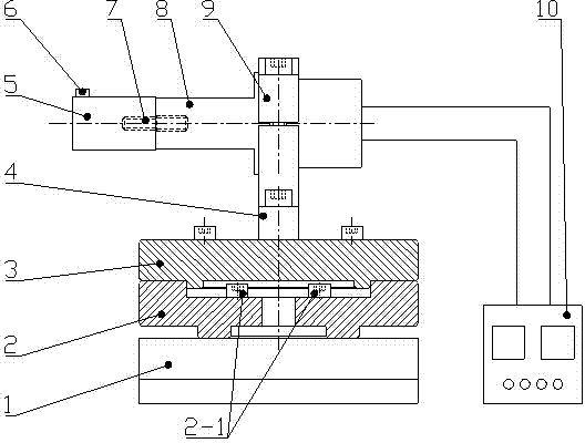
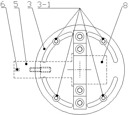
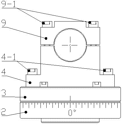
[0021] Such as Figure 1 to Figure 3 As shown, a variable-angle ultrasonic vibration-assisted grinding device for ultra-precision machining, including a Kistler dynamometer 1, a lower base 2 of a disc-shaped rotary table, an upper base 3 of a disc-shaped rotary table, and a luffing Rod clamping device lower base 4, horn clamping device upper base 9, horn 8, workpiece support 5, ultrasonic generator 10 and screws 2-1, 3-1, 4-1 for connection , 9-1 and stud 7.

[0022] The lower base 2 of the disc-shaped rotary table and the upper base 3 of the disc-shaped rotary table are placed on the dynamometer 1, the lower base 4 of the horn clamping device and the upper base 9 of the horn clamping device are fixed on the disc-shaped The upper base 3 of the rotary table, the lower base 2 of the disc-shaped rotary table and the upper base 3 of the disc-shaped rotary...


PUM


Abstract

The invention relates to a variable angle supersonic vibration auxiliary grinding device for precision and ultra-precision machining. The variable angle supersonic vibration auxiliary grinding device for precision and ultra-precision machining comprises the following parts arranged on a measuring cell including a disc-shaped rotating table lower base and a disc-shaped rotating table upper base, an amplitude-change pole clamping device lower base and an amplitude-change pole clamping device upper base, and an ultrasonic generator and a workpiece support table which are connected to a amplitude-change pole, wherein concentric locating is conducted between the disc-shaped rotating table lower base and the disc-shaped rotating table upper base, the disc-shaped rotating table lower base is connected with the disc-shaped rotating table upper base in a rotating mode, and the middle portions of the amplitude-change pole clamping device lower base and the amplitude-change pole clamping device upper base are folded to fixedly clamp the amplitude-change pole. According to the variable angle supersonic vibration auxiliary grinding device for precision and ultra-precision machining, supersonic vibration in any direction can be achieved through the accurate rotation of the rotating table upper base and the rotating table lower base; meanwhile, a workpiece support table platform is facilitated to be adjusted to horizontal by the adoption of the folding clamping mode; the measuring cell is only connected with the rotating table lower base, and therefore it is guaranteed that the amplitude-change pole is still capable of measuring the force of a grinding wheel in three directions when the amplitude-change pole rotates at any angle; the variable angle supersonic vibration auxiliary grinding device for precision and ultra-precision machining is applicable to the precision and ultra-precision machining of hard brittle materials and part of alloy materials.

Description

technical field [0001] The invention relates to a variable-angle ultrasonic vibration-assisted grinding device, in particular to a grinding device for hard and brittle materials such as optical glass, ceramics, and sapphire, as well as hard or heat-resistant conductive metal materials such as hardened steel and hard alloy. Ultrasonic vibration assisted grinding device for precision ultra-precision grinding. Background technique [0002] Optical glass is widely used in many modern high-tech industries such as aerospace, information, microelectronics and surveying and mapping because of its high temperature resistance, low expansion coefficient, high mechanical strength, and good chemical properties. However, due to the high hardness, high strength, and brittle texture of optical glass, the traditional cutting processing methods are not suitable for processing tasks, so the precision and ultra-precision machining of these materials has become an important research direction in...

Claims


Application Information

Patent Timeline
Patent Type & Authority Applications(China)
IPC IPC(8): B24B1/04B24B49/16
CPCB24B1/04B24B49/165
Inventor 王艳王帅胡捷飞王健波水洪伟谢建华秦琛彭水平
Owner UNIV OF SHANGHAI FOR SCI & TECH
Why Eureka
Try Eureka