Pressure die casting mold for producing a casting

A technology of die-casting molds and castings, applied in the direction of die-casting molds, manufacturing tools, molds, etc., can solve the problems of cost, manufacturing and processing troubles, and achieve the effect of simplifying processing and speeding up manufacturing

Active Publication Date: 2015-07-01
DURAVIT AG
View PDF6 Cites 10 Cited by
  • Summary
  • Abstract
  • Description
  • Claims
  • Application Information

AI Technical Summary

Problems solved by technology

[0003] Apart from the fact that the bond line is ultimately not desired, the manufacture and handling of the three separate parts to manufacture such a one-piece toilet is cumbersome and costly

Method used


Image

  • Pressure die casting mold for producing a casting
  • Pressure die casting mold for producing a casting
  • Pressure die casting mold for producing a casting

Examples


Embodiment Construction

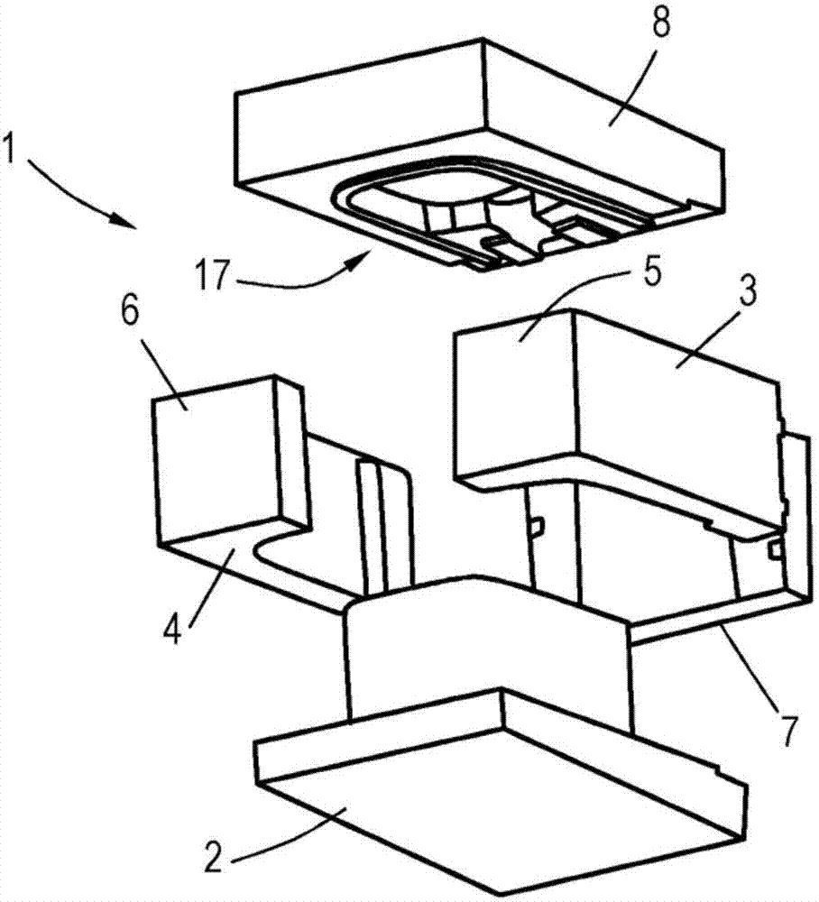
[0030] figure 1 An injection molding die 1 according to the invention is shown in an exploded view, comprising a bottom part 2, two side parts 3, 4, as well as a rear wall 7 and a cover part 8, on which the halves of the front wall are respectively arranged 5,6. In the closed state, the mold parts define a cavity in which a cast part is produced, said cast part comprising a water ring and a water reservoir, wherein the two form a one-piece cast part.

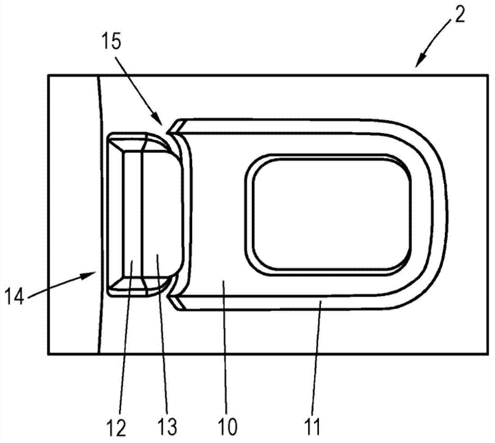
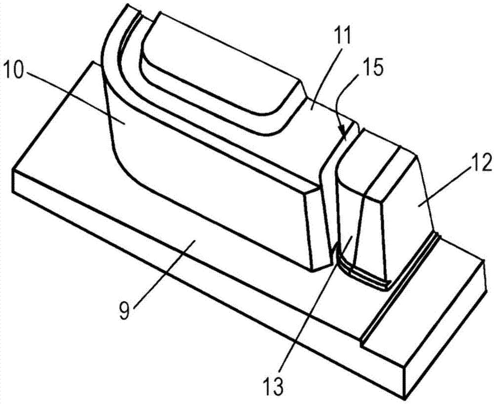
[0031] Figures 2 to 4 The bottom part 2 is shown in plan view and sectional view. The bottom part consists of a base plate 9 and a shaped body 10 protruding from the base plate, the upper side of which is designed with a shaped structure 11 for forming a water ring. Adjacent to the shaped body 10 is a first wedge-shaped element 12 protruding outwards from the base plate 9 . Adjacent to this first wedge element, a detachable, ie separate, second wedge element 13 is arranged. The wedge elements 12, 13 complementarily form a ...


PUM


Abstract

A pressure die casting mold for producing a casting which is part of an integral toilet having a body, a water ring, and a tank, wherein the casting, as an integral component, includes the water ring and the tank which is open on the upper side. The pressure die casting mold is composed of at least five molded parts which are interconnectable in a releasable manner, namely of a base part, two side parts having in each case one half of a front wall, a rear wall, and a cover part. The molded parts delimit a cavity which corresponds to the outer shape of the casting. A wedge element, which at least in portions delimits the inner shape of the water tank, is provided on the base part.

Description

technical field [0001] The invention relates to a die-casting mold for the manufacture of a casting which is part of a one-piece toilet comprising a body, a water ring and a cistern, wherein the casting has a water ring and a cistern open on the upper side as a one-piece component box. Background technique [0002] "One-piece toilet" is understood as a sanitary fitting, generally made of ceramic or porcelain, which ultimately consists of three components, namely on the one hand the real body, which includes the bowl-shaped area and the corresponding measures serving as the connecting sleeve and Corresponding fastening means, either for bottom-side arrangement or for wall-side mounting. The second part is the so-called water ring, which is placed on the main body on the upper side and serves to distribute the flushing water. Finally, the third part is the water storage tank, which is also placed on the body side and through which the flushing water reaches the water ring. ...

Claims


Application Information

Patent Timeline
Patent Type & Authority Applications(China)
IPC IPC(8): B28B7/00B28B3/04
CPCE03D1/01B28B1/261B28B1/002B28B1/24E03D11/02B28B7/0002B28B7/16B28B3/04B28B7/0097B28B1/265E03D1/012B28B7/0029B28B7/20B28B7/26B28B7/12B29C33/48B29C33/485
Inventor J·A·德 拉 科特C·莱德曼
Owner DURAVIT AG
Why Eureka
Try Eureka