
A device and method for separating antimony-containing alloys

An antimony alloy and molten pool technology is applied in the field of devices for separating antimony-containing alloys, and can solve the problems of difficult operation, no use value, and large loss of molten salt volatilization.

Active Publication Date: 2017-06-06
锡矿山闪星锑业有限责任公司
View PDF6 Cites 0 Cited by
  • Summary
  • Abstract
  • Description
  • Claims
  • Application Information

AI Technical Summary

Problems solved by technology

This method is used to produce high-purity antimony, which requires low impurity content in crude antimony. If the impurity content is too high, its efficiency will be reduced a lot. At the same time, the electrolysis time will be longer. To obtain 99.99% metal antimony, the direct recovery rate It will be extremely low and has no use value. Therefore, this method is not suitable for the treatment of crude antimony electrolysis with high impurity content.
In addition, the electrolytic cell still has the following disadvantages: one is electrolysis at 700-900 ° C, the molten salt is extremely volatile, and without a reflux device, the loss of molten salt volatilization is extremely large, resulting in environmental deterioration; the other is electrolysis The cathode and anode electrodes in the tank are in the same molten pool, and the cathode and anode products after electrolysis are inconvenient to separate and remove, resulting in difficult operation, and even easy to confuse the cathode and anode products

Method used


Image

  • A device and method for separating antimony-containing alloys
  • A device and method for separating antimony-containing alloys
  • A device and method for separating antimony-containing alloys

Examples


Embodiment Construction

[0045] The present invention will be further described below in conjunction with the embodiments and accompanying drawings.

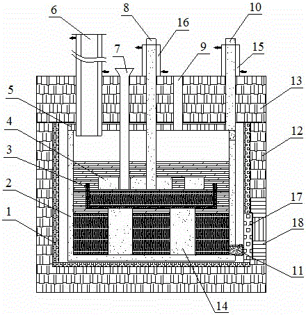
[0046] At first introduce the structure of the device embodiment of separating high lead-antimony alloy or noble antimony of the present invention:

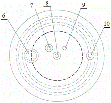
[0047] Such as figure 1 As shown, it includes heating furnace 1, cathode molten pool 2, anode molten pool 3, anode plate 4 with openings, return pipe 6, hopper 7, anode graphite rod 8, cathode graphite rod 10 and cathode slag discharge valve 11. Both the cathode molten pool 2 and the anode plate 4 are made of graphite, and the cathode slag discharge valve 11 is a graphite sealing plug with interference fit; the cathode molten pool 2 is located in the heating furnace 1 and covered with the cathode molten pool Cover plate 5, the cathode molten pool cover plate 5 is connected to the cathode graphite rod 10; the anode molten pool 3 is suspended in the cathode molten pool 2, the anode graphite rod 8 passes th...


PUM

PropertyMeasurementUnit
melting pointaaaaaaaaaa

Abstract

The invention discloses a device and method for separating an antimony-containing alloy. The device comprises a heating furnace, a cathode melting bath, an anode melting bath, an anode plate provided with openings, a cathode melting bath cover plate, a return pipe, a feeding hopper, an anode bar, a cathode bar, a cathode slag discharging valve, a heat preserving furnace, a heat preserving furnace cover plate, an anode melting bath supporting seat, a cathode bar cooling jacket, an anode bar cooling jacket, a heating furnace movable door and a heat preserving furnace movable door. The method comprises the following steps: melting the antimony-containing alloy, namely preparing a molten salt, adding into the melting baths gradually, heating, adding the antimony-containing alloy after melting of the molten salt, and melting; and (2) electrolyzing the molten salt, namely performing electrolysis by switching on a direct-current power supply, and discharging cathode residues and anode residues respectively after electrolysis. The anode residues can be further chloridized and subjected to displacement reduction to extract metals. The process disclosed by the invention is environment-friendly, the recovery rate of the separated antimony-containing alloy is more than or equal to 99%, and the direct recovery rate of gold and silver in the antimony-containing alloy reaches 99.9%, so that the device and the method are suitable for separating various antimony-containing alloys.

Description

technical field [0001] The invention relates to a device and method for separating antimony-containing alloys, in particular to a device for separating impurity metals such as lead, copper, nickel or antimony from antimony-containing alloys by using molten salt electrolysis, enriching gold and silver, and recovering antimony. method. Background technique [0002] Antimony-containing alloys are a by-product of the smelting process of antimony-containing non-ferrous metals (including precious metals), such as lead-antimony alloys obtained after smelting high-lead antimony ores, and noble antimony obtained after smelting gold-containing antimony ores. The production process of noble antimony is as follows: during the pyromelting process of antimony-gold concentrate, gold and silver are initially enriched to obtain noble antimony containing gold and silver, and further volatilization and blowing are carried out to obtain rich antimony with higher gold and silver content. The ge...

Claims


Application Information

Patent Timeline
Patent Type & Authority Patents(China)
IPC IPC(8): C25C3/34
CPCC25C3/34
Inventor 单桃云廖光荣刘鹊鸣戴永俊邓卫华金承永姚兴娜姚芾曾雁
Owner 锡矿山闪星锑业有限责任公司
Learn More