
Pressurized roof communication tower and its installation method

A communication tower and roof technology, applied in the field of roof communication tower and installation, weighted roof communication tower and installation, can solve the problem of communication tower dismantling, difficulty in moving, long construction period of communication tower, poor mobility of communication tower, etc. problems, to achieve the effect of easy acceptance by the other party, convenient transportation, and reduction of erection costs

Active Publication Date: 2017-02-22
VALMONT IND CHINA +1
View PDF8 Cites 0 Cited by
  • Summary
  • Abstract
  • Description
  • Claims
  • Application Information

AI Technical Summary

Problems solved by technology

However, the above-mentioned communication tower has a long construction period, and the damage to the original floor is relatively large, which may easily cause water seepage or structural damage to the original structure, and cause opposition from the building owner, and cause a safety hazard to the building; in addition, the above-mentioned method has high construction costs. , high strength, easy to generate construction waste, after the communication tower is completed, it is difficult to dismantle and move, and the mobility of the communication tower is poor, so it cannot be moved quickly according to actual needs

Method used


Image

  • Pressurized roof communication tower and its installation method
  • Pressurized roof communication tower and its installation method
  • Pressurized roof communication tower and its installation method

Examples


Embodiment Construction

[0028] The present invention will be described in further detail below in conjunction with the accompanying drawings.

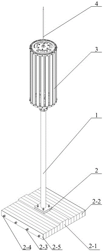
[0029] Such as Figures 1 to 5 As shown, the pressure-heavy roof communication tower of the present invention is mainly erected on the roof or roof as a carrier for antenna installation of various operators. Including column 1, base 2, radome steel structure 3 and lightning rod 4. The column 1 is connected and fixed with the base 2 through the connecting flange at the bottom, and the connecting flange at the top of the column 1 is connected with the radome steel structure 3, which is used for installing various antennas; the lightning rod 4 is connected with the top of the antenna mounting frame 3 Flange connection. A plurality of glass steel bars are installed on the outer circumference of the radome steel structure 3, which has good wave permeability, strong outdoor aging resistance, and good wind resistance, which can strengthen the protection of the int...


PUM


Abstract

The invention discloses a pressure weight type roof communication tower and a mounting method, and belongs to the field of communication devices. The pressure weight type roof communication tower comprises a stand column, an antenna mounting frame and a base. The stand column is mounted on the base, and the antenna mounting frame is mounted on the upper portion of the stand column. The base comprises a main base, an auxiliary base and a connecting device, the auxiliary base is composed of multiple concrete auxiliary blocks, and the concrete auxiliary blocks are symmetrically arranged on the two sides of the main base. A connecting portion connected with the stand column is arranged on the main base, and multiple transverse through holes are formed in the side face of the main base. Multiple transverse through holes are formed in the side faces of the concrete auxiliary blocks, and the concrete auxiliary blocks are correspondingly communicated with the positions of the transverse through holes in the main base. The concrete auxiliary blocks and the main base are connected in to a whole through the connecting device. A modular structure is integrally adopted by the communication tower, the communication tower is convenient to carry, site construction is easy, damage on an existing roof structure is avoided, the pressure weight type roof communication tower can be mounted on roofs of different structures rapidly, and safety of buildings with the pressure weight type roof communication tower erected is guaranteed.

Description

technical field [0001] The invention relates to a communication tower on the roof of a building and an installation method thereof, in particular to a communication tower of a pressure-weight type roof communication tower and an installation method thereof, belonging to the field of communication equipment. Background technique [0002] With the rapid development of wireless communication technology and the construction of 3G / 4G wireless networks, the requirements for seamless coverage of urban signals are getting higher and higher, and the construction of dense urban stations has become inevitable. [0003] In the process of urban base station construction, in order to avoid the influence of high-rise buildings and ensure normal signal coverage, it is usually selected on the roof of existing high-rise buildings. The current practice is to smash the outer concrete of the main beam on the load-bearing column and implant steel bars Place the anchors in the original structural ...

Claims


Application Information

Patent Timeline
Patent Type & Authority Patents(China)
IPC IPC(8): E04H12/00E04H12/22
CPCE04H12/2238E04H12/2261
Inventor 郑宏李晋王江川卢伟滕鸿飞
Owner VALMONT IND CHINA
Learn More