
Device and method for measuring thermo-optical coefficient of thin-film material

A thin-film material, thermo-optic coefficient technology, applied in the field of testing, can solve the problems of difficult determination of physical parameters, affecting measurement accuracy, discontinuous testing process, etc., to achieve the effect of wide application, easy implementation and easy method.

Inactive Publication Date: 2015-07-01
UNIV OF ELECTRONICS SCI & TECH OF CHINA
View PDF5 Cites 13 Cited by
  • Summary
  • Abstract
  • Description
  • Claims
  • Application Information

AI Technical Summary

Problems solved by technology

However, the indirect measurement method needs to build an optical experiment platform, purchase optical instruments and adjust the optical path for each test, resulting in the discontinuity of the entire test process, which takes a long time and seriously affects the measurement accuracy
However, for the thermo-optic coefficient expression obtained by the modeling calculation method, it is difficult to establish an ideal physical model, and the physical parameters in the model are not easy to determine, so it is rarely used in practice.

Method used


Image

  • Device and method for measuring thermo-optical coefficient of thin-film material
  • Device and method for measuring thermo-optical coefficient of thin-film material

Examples


Embodiment

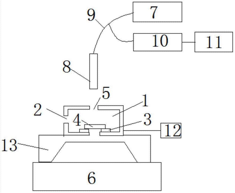
[0035] Such as figure 1As shown, in the device for measuring the thermo-optic coefficient of thin film materials in this example, the air inlet of the heating unit is located on the side wall of the box, the light opening is located on the top of the box, and the heating plate is arranged at the bottom of the box. The heating plate is silicon Rubber heating plate 3. The silicone rubber heating plate 3 can ensure that the film material 4 to be measured is heated evenly. Silicone rubber heating plate has rapid heating, high thermal efficiency, water resistance, acid resistance, alkali resistance, high electrical insulation strength, wide temperature range, from -60°C to 200°C and self-insulation, no open flame, great for heat preservation and heat insulation in technology For simplification, easy to use and other features.

[0036] The light opening 5 is located above the heating plate, and the thin film material 4 to be measured is erected on the heating plate to ensure that ...


PUM


Abstract

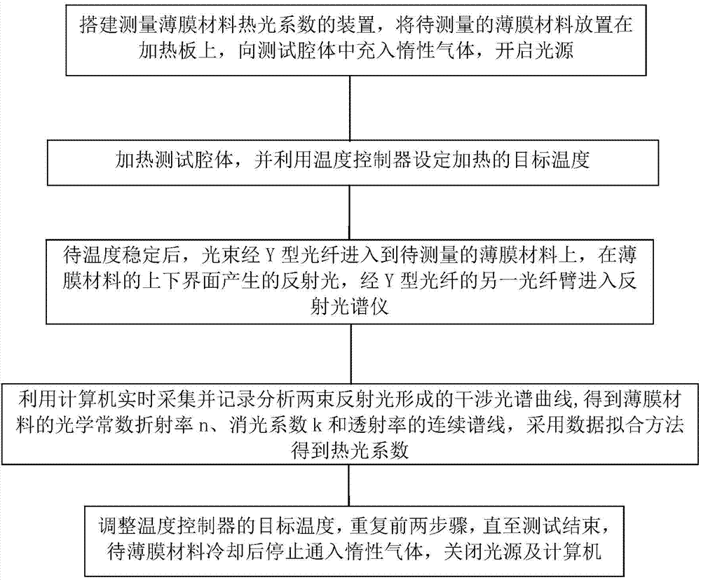
The invention discloses a device and a method for measuring the thermo-optical coefficient of a thin-film material, and belongs to the technical field of tests. The invention provides a device and a method capable of directly and rapidly measuring a thermo-optical coefficient. The device comprises a workbench, a light source, a Y-shaped optical fibre, a reflection frequency spectrometer and a computer, wherein the two optical fibre arms of the Y-shaped optical fibre are connected with the light source and the reflection frequency spectrometer respectively, and the reflection frequency spectrometer is connected with the computer. The device further comprises a support frame and a heating unit, wherein the heating unit is erected on the workbench through the support frame; the heating unit comprises a box; a test cavity is formed in the box; an air inlet hole and a light passing hole are formed in the box; a heating plate is placed in the test cavity; the common end of the Y-shaped optical fibre is located above the light passing hole; the light passing hole corresponds to the heating plate in position. The device further comprises a temperature controller connected with the test cavity. The device is capable of obtaining the continuous spectral lines of the optical constant and the transmissivity of a film at different temperatures without breakages to the surface of the film through non-contact measurement, high in measurement accuracy, and suitable for measuring the thermo-optical coefficient of a film material.

Description

technical field [0001] The invention belongs to the technical field of testing and relates to a device and method for measuring the thermo-optic coefficient of thin film materials. Background technique [0002] The thermo-optic effect of thin film materials refers to the physical effect that the optical properties of the material change with the change of temperature, and its characterization is the thermo-optic coefficient. The thermo-optic properties of thin-film materials are widely used in the field of optoelectronic devices. In order to improve and guide the production and production process of optical materials, it is necessary to measure the thermo-optic coefficient of thin film materials. In addition, studying the thermo-optic coefficient can further improve the quality of precision optical instruments and lasers. [0003] The traditional measurement method of thermo-optic coefficient is as follows: (1) Indirect measurement method: at different temperatures, by meas...

Claims


Application Information

Patent Timeline
Patent Type & Authority Applications(China)
IPC IPC(8): G01N21/25G01N21/45G01N21/59
Inventor 刘爽周湘陈逢彬刘云飞熊流峰钟智勇刘永
Owner UNIV OF ELECTRONICS SCI & TECH OF CHINA
Learn More