Urban traffic signal control running diagnostic system

A traffic signal and diagnosis system technology, applied in the field of traffic signal control, can solve problems such as ignoring applicability, large errors, and difficult to measure indicators such as average vehicle delay, achieving low cost and comprehensive evaluation indicators

Inactive Publication Date: 2015-07-01
TONGJI UNIV
View PDF7 Cites 14 Cited by
  • Summary
  • Abstract
  • Description
  • Claims
  • Application Information

AI Technical Summary

Problems solved by technology

[0004] 1. At present, the signal control systems used in major cities in my country are mainly foreign ones, copying the operation mode of foreign systems and ignoring their applicability, because there are large differences in domestic and foreign traffic flows, especially domestic non-motor vehicles and high proportion of pedestrians;
[0005] 2. In China, the selection of various methods and parameters in the signal control system is often based on empirical knowledge as the basis for selection and judgment, lacking theoretical support;
[0006] 3. After the signal control system has been in operation for a long period of time, there is a certain deviation between the actual measured value of the system operation and the set theoretical value, but there is still a lack of effective and objective diagnosis and evaluation system for the existing signal control operation in China
However, indicators such as the average vehicle delay are relatively difficult to measure, and the theoretical calculation results have a larger error than the real value.
In addition, on the one hand, these existing indicators cannot fully and accurately reflect the operation status of traffic flow at intersections; on the other hand, these indicators only consider the results of signal control operations, and do not consider the pros and cons of the intermediate control parameters that lead to these results

Method used


Image

  • Urban traffic signal control running diagnostic system
  • Urban traffic signal control running diagnostic system
  • Urban traffic signal control running diagnostic system

Examples


Embodiment 1

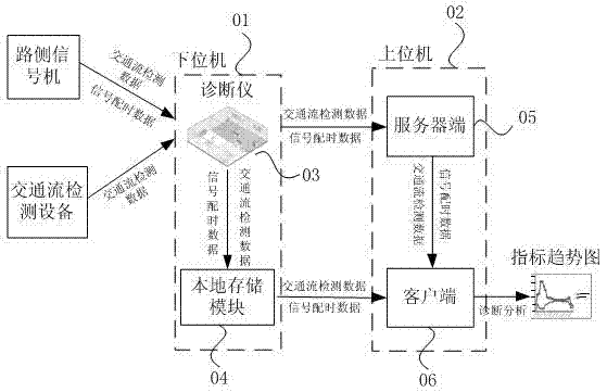
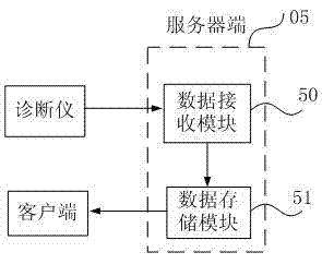
[0036] Such as Figure 1-Figure 4 As shown, it is mainly composed of two parts: the lower computer 01 and the upper computer 02. The lower computer 01 is the diagnostic instrument 03, which is mainly composed of embedded microcontrollers, serial communication, wireless communication, SD cards and other hardware devices; the upper computer 02 is mainly Including server 05 and client 06, of which:

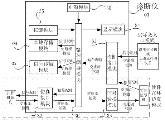
[0037] The diagnostic instrument 03 is composed of a power supply module, key module, display module, diagnostic interface module, simulation interface module, signal conversion module, microcontroller module, information transmission and local storage module, and the diagnostic instrument 03 can be switched to the actual crossover through the key module There are two different working modes of interface and hardware-in-the-loop simulation, which are used to diagnose the actual traffic signal control operation and the traffic signal control operation based on hardware-in-the-loop res...


PUM


Abstract

The invention relates to an urban traffic signal control running diagnostic system, and refers to the technical field of traffic signal control and traffic simulation. The urban traffic signal control running diagnostic system aims to provide comprehensive, subjective and quantitative diagnostic evaluation for the existing signal control system. The diagnostic system is mainly composed of a lower computer and an upper computer, wherein the lower computer is a diagnostic machine; the diagnostic system is connected with a road side signal machine, the other traffic flow detector or a computer, so as to read the traffic flow detection data and signal timing dial data in real time under the reality or hardware-in-loop simulation environment, and also perform the local storage, upload server, and other operation; the upper computer mainly includes a server end and a client end, wherein the server end can store the data sent by the diagnostic machine, and the client end can load corresponding data from the server end as well as a local memory card, so as to calculate the change trend of the diagnostic index within a certain time section and provide a report for improvement suggestions; thus the urban traffic signal control running diagnostic system can provide an intuitional and visible diagnostic effect for managers.

Description

technical field [0001] The invention belongs to the technical field of traffic signal control, and is mainly applied to the scientific diagnosis and evaluation of the operation state and effect of the urban road traffic signal control system, and can be used as an experimental teaching tool for students majoring in traffic engineering. Background technique [0002] Urban traffic signal control, as the core means to alleviate intersection congestion and improve traffic flow safety, plays a key role in the traffic system. On the one hand, it improves vehicle traffic capacity and reduces delay time through an optimized signal control strategy; on the other hand, it can ensure the safety of vehicles and pedestrians by regulating key parameters during signal phase switching. Therefore, the quality of the signal control system is directly related to the safety and efficiency of the road system. [0003] However, in the actual operation of urban road traffic systems, the following...

Claims


Application Information

Patent Timeline
Patent Type & Authority Applications(China)
IPC IPC(8): G08G1/097
CPCG08G1/097
Inventor 孙剑陈灿汪建兵
Owner TONGJI UNIV
Why Eureka
Try Eureka