Gas-propelled self-stirring combined purification tank

A purification tank and push-type technology, which is applied in gas production bioreactors, bioreactor/fermenter combinations, mixers, etc. The effect of reducing production costs, facilitating application and promotion, and accelerating purification and processing speed

A purification tank and push-type technology, which is applied in gas production bioreactors, bioreactor/fermenter combinations, mixers, etc. The effect of reducing production costs, facilitating application and promotion, and accelerating purification and processing speed

CN104759228BActive Publication Date: 2016-09-14李玲 +1

Image

  • Gas-propelled self-stirring combined purification tank
  • Gas-propelled self-stirring combined purification tank
  • Gas-propelled self-stirring combined purification tank

Examples


Embodiment Construction

[0017] The present invention will be further described below in conjunction with the accompanying drawings and embodiments.

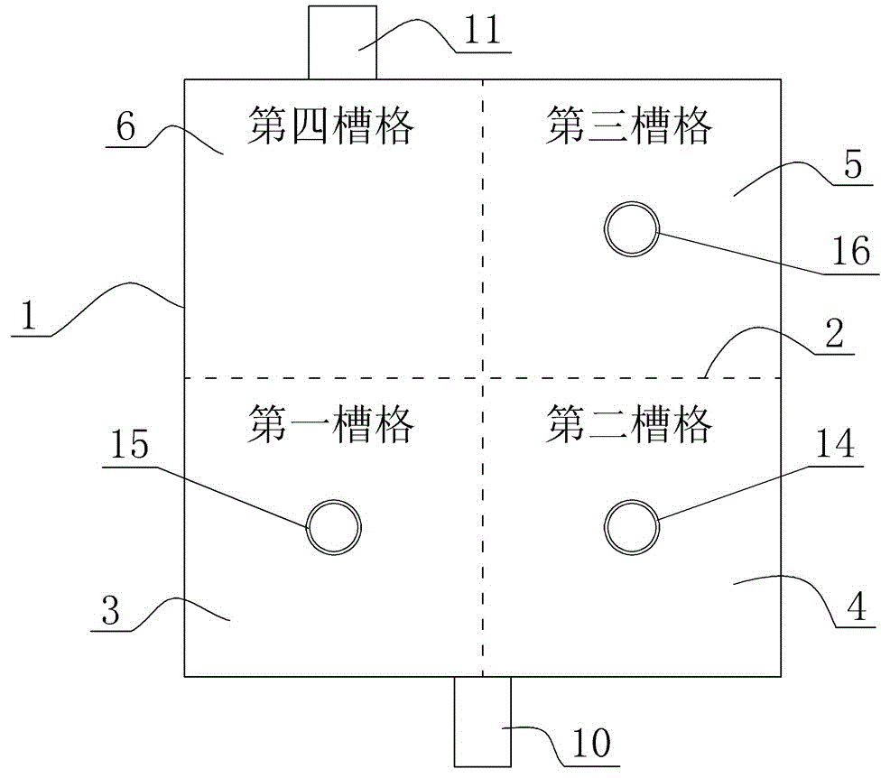
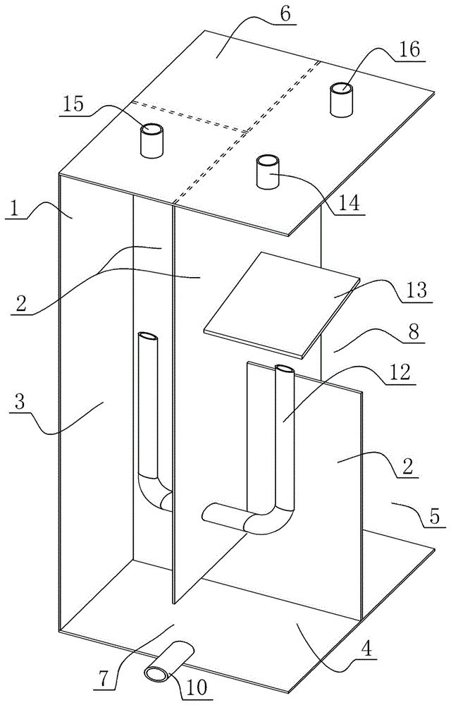
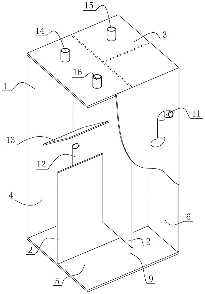
[0018] Such as figure 1 As shown, the principle diagram of the gas-propelled self-stirring combined purification tank of the present invention is provided, figure 2 and image 3 Its three-dimensional structure diagram is given, and the combined purification tank shown includes an outer wall 1, a partition plate 2, a feed pipe 10, a discharge pipe 11, a U-shaped pipe 12, an air guide plate 13, a gas outlet 14, and a first gas circulation Port 15 and second gas circulation port 16; the interior of the outer wall 1 shown is a cavity, and the partition plate 2 divides the cavity in the outer wall 1 evenly into a first cell 3, a second cell 4, and a third cell 5 and the fourth slot 6. The lower end of the partition between the first cell 3 and the second cell 4 is provided with a first opening 7, while the U-shaped pipe 12 is arranged on the partition be...


PUM


Abstract

The gas-propelled self-stirring combined purification tank of the present invention includes an outer wall and a partition arranged in the outer wall, and the partition divides the inner cavity of the outer wall into first, second, third and fourth cells; it is characterized in that: A first opening is provided between the first and second slots, a second opening is provided between the second and third slots, and a third opening is provided between the third and fourth slots; the first opening is provided with There is a feed pipe, and a discharge pipe is provided in the middle and upper part of the fourth cell; a U-shaped tube that can automatically stir the matrix is ​​arranged on the partition between the first cell and the second cell. In the combined purification tank of the present invention, a U-shaped tube is arranged on the dividing plate between the first cell and the second cell to realize the automatic stirring function of the substrate, and accelerate the purification and processing speed of the substrate; Adding the auxiliary stirring device simplifies the structure of the purification tank, reduces the production cost, has remarkable beneficial effects, and is convenient for application and popularization.

Description

technical field [0001] The invention relates to a gas-propelled self-stirring combined purification tank, more specifically, to a combined purification tank which uses gas to periodically stir the substrate during the substrate purification process. Background technique [0002] The existing high-concentration organic waste generally adopts anaerobic fermentation process to produce biogas while treating the waste. However, in order to ensure the normal operation of the treatment facility, stirring equipment must be installed in the reaction tank, which not only increases the complexity of the structure, but also increases the operating cost. Seriously restrict the popularization and application scope of its technology. [0003] In terms of sewage treatment, there is a lack of a suitable method, which has a simple structure and can achieve the effect of simultaneous denitrification and phosphorus removal. The problem that needs to be solved urgently is: there is no pollutan...

Claims


Application Information

Patent Timeline
14 Sep 2016
Publication
CN104759228B
IPC
B01F13/02; C02F3/28; C12M1/107; C12M1/02; B01F33/40
Inventors
戚伟康; 李玉友