Ground high-low pressure mixed gas-liquid separation system based on multi-reservoir commingling production gas field

A high-low pressure, mixed gas technology, applied in the fields of fluid production, earth-moving drilling, wellbore/well components, etc., can solve the problems of equipment waste, increased engineering cost, idleness, etc.

Active Publication Date: 2015-07-08
XIAN CHANGQING TECH ENG
View PDF6 Cites 1 Cited by
  • Summary
  • Abstract
  • Description
  • Claims
  • Application Information

AI Technical Summary

Problems solved by technology

In the stage of high-pressure production, the gas-gathering station needs to install a high-pressure separator to realize the separation of gas and liquid. In order to meet the needs of low-pressure production, it is often necessary to install an additional low-pressure separator. A large number of separators will be left idle, resulting in waste of equipment and increase in engineering costs

Method used


Image

  • Ground high-low pressure mixed gas-liquid separation system based on multi-reservoir commingling production gas field
  • Ground high-low pressure mixed gas-liquid separation system based on multi-reservoir commingling production gas field
  • Ground high-low pressure mixed gas-liquid separation system based on multi-reservoir commingling production gas field

Examples


Embodiment 1

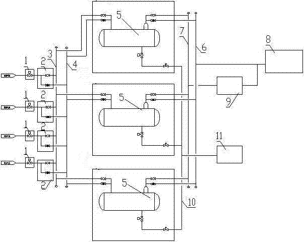
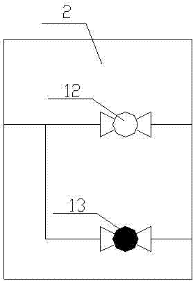
[0019] This embodiment provides a ground high-low pressure mixed gas-liquid separation system based on a multi-reservoir co-production gas field, which includes an air inlet pipeline and a gas-liquid separator 5, and an inlet cut-off valve 11 is arranged on the inlet pipeline, and the The outlet end of the entry cut-off valve 11 is connected with a high-low pressure flow switching valve group 2, and the high-low pressure flow switching valve group 2 is composed of a high-pressure flow control valve 12 and a low-pressure flow control valve connected in parallel with the exit end of the entry cut-off valve 11. 13 composition;

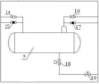
[0020] The high-pressure process control valve 12 communicates with the inlet end of the gas-liquid separator 5 through the high-pressure gas collecting pipe 3 before separation, and the high-pressure gas collecting pipe 3 before separation is provided with a separator inlet high-pressure flow control valve 14, and the gas-liquid separation The gas phase ...

Embodiment 2

[0027] On the basis of Embodiment 1, a flow meter 8 is connected to the outlet end of the high-pressure gas manifold 6 after separation; a natural gas compressor 9 is connected to the outlet end of the low-pressure gas manifold 7 after separation, and the outlet end of the natural gas compressor 9 communicates with the flow meter 8 .

[0028] In this embodiment, the flow meter 8 can meet the flow measurement requirements of natural gas. After separation, the natural gas compressor 9 connected to the outlet end of the low-pressure gas manifold 7 can increase the low-pressure natural gas to a high-pressure level, and connect to the flow meter 8 for flow measurement after pressurization.

Embodiment 3

[0030] This embodiment provides a figure 1 In the shown ground high-pressure and low-pressure mixed gas-liquid separation system based on the multi-reservoir co-production gas field, multiple sets of the mixed gas-liquid separation system are arranged side by side in this embodiment to meet different requirements at the same time.

[0031] Such as figure 1 As shown, the inbound natural gas first enters the inbound shut-off valve 11 through the intake pipeline, and the inbound shut-off valve 11 communicates with the inlet port of the high-low pressure process switching valve group 2, and the high-pressure process control valve 12 at the outlet end of the high-low pressure process switching valve group 2 and The low-pressure process control valve 13 communicates with the high-pressure gas manifold 3 before separation and the low-pressure gas manifold 4 before separation, respectively, and the high-pressure gas manifold 3 before separation and the low-pressure gas manifold 4 befo...


PUM


Abstract

The invention provides a ground high-low pressure mixed gas-liquid separation system based on a multi-reservoir commingling production gas field. The ground high-low pressure mixed gas-liquid separation system comprises a gas inlet pipeline and a gas-liquid separator; an in-station block valve is arranged on the gas inlet pipeline; the outlet end of the in-station block valve is communicated with a high-low flow switching valve bank; the high-low flow switching valve bank is composed of a high-pressure flow control valve and a low-pressure flow control valve, the two of which are communicated in parallel to the outlet end of the in-station block valve. The ground high-low pressure mixed gas-liquid separation system is capable of simultaneously meeting the natural gas-liquid separation requirements in different production manners such as total high-pressure production, high-low pressure mixed production and total low-pressure production.

Description

technical field [0001] The invention belongs to the technical field of gas-liquid separation, and in particular relates to a ground high-low pressure mixed gas-liquid separation system based on a multi-reservoir co-production gas field. Background technique [0002] In the process of gas field development, developers often adopt different development methods according to the different pressure characteristics of gas reservoirs, and different development methods determine different pressure systems for surface gathering and transportation. Some gas fields adopt multi-layer system development methods, and different layer systems have different gas reservoir characteristics and development methods. In this way, there are often more than one pressure system for surface gathering and transportation. [0003] In order to quickly recover development costs and maximize benefits, gas wells with high production and slow gas reservoir pressure deceleration rate often adopt the producti...

Claims


Application Information

Patent Timeline
IPC IPC(8): E21B43/34
CPCE21B43/34
Inventor 刘明堃杨光王登海郑欣刘银春范君来胡涛乔光辉李强李鹏江
Owner XIAN CHANGQING TECH ENG
Why Eureka
Try Eureka