An intelligent dynamic balancing device for a high-speed spindle machine

A high-speed spindle and balancing device technology, applied in static/dynamic balance testing, measuring devices, vibration testing, etc., can solve problems such as low degree of automation, inability to simulate high-speed operation, and low efficiency of dynamic balancing, and achieve intelligent dynamic balance. Balance, improve dynamic balance accuracy and efficiency, and improve the effect of dynamic balance accuracy

Active Publication Date: 2017-10-17
XIDIAN UNIV
View PDF5 Cites 0 Cited by
  • Summary
  • Abstract
  • Description
  • Claims
  • Application Information

AI Technical Summary

Problems solved by technology

[0006] The purpose of the present invention is to provide an intelligent dynamic balancing device for a high-speed spindle, which overcomes the disadvantages of the existing high-speed spindle offline dynamic balancing, such as low efficiency, inability to simulate a high-speed running state, and a low degree of automation, and effectively improves the dynamic balancing efficiency of a high-speed spindle and precision

Method used


Image

  • An intelligent dynamic balancing device for a high-speed spindle machine
  • An intelligent dynamic balancing device for a high-speed spindle machine
  • An intelligent dynamic balancing device for a high-speed spindle machine

Examples


Embodiment 1

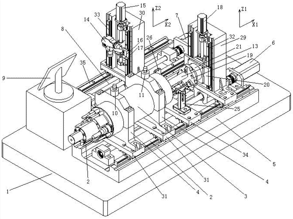
[0035] likefigure 1 As shown, the present invention provides an intelligent dynamic balancing device for a high-speed spindle machine, which includes a bottom plate 1 and is characterized in that it also includes a fixed connection part of the spindle system, an automatic rotor clamping and rotating part, a laser automatic Alignment and deduplication part, unbalance detection part;

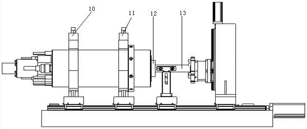
[0036] The fixed coupling part of the spindle system includes a high-speed spindle 3, a spindle positioning seat 4 for fixing the high-speed spindle 3, and a spindle area base 5; wherein the spindle positioning seat 4 and the spindle area base 5 fixed on the base plate 1 are fixed in the spindle area The X1 direction guide rail 2 on the base 5 is slidably connected, and the position of the spindle positioning seat 4 on the base 5 in the spindle area can be fixed; the structure diagram of the spindle area is shown in figure 2 shown.

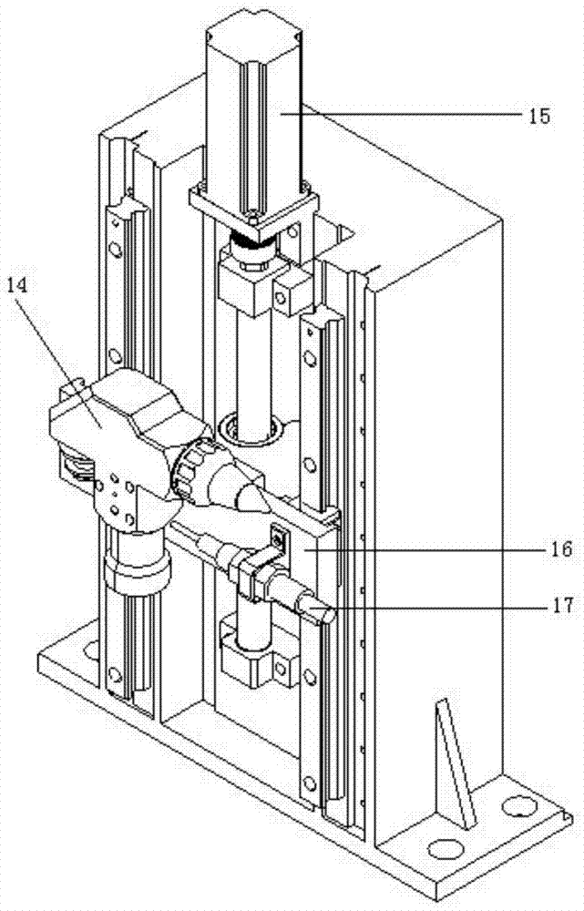
[0037] see Figure 4 , the rotor automatic clamping and rotat...

Embodiment 2

[0041] On the basis of Embodiment 1, the spindle positioning seat 4 is slidingly connected to the spindle area base 5 fixed on the bottom plate 1, and the position of the spindle positioning seat 4 on the spindle area base 5 can be fixed. The structure is: the main shaft positioning seat 4 is fixedly connected with the guide rail slider one 31, the guide rail slider one 31 is slidingly connected with the X1 direction guide rail 2, and the guide rail slider one 31 can be fixed on the X1 direction guide rail 2, specifically the guide rail slider one 31 is fixed between the pin and the X1 direction guide rail 2.

[0042] The Z1 direction workbench 20 is slidably connected along the Z1 direction on the Z1 direction base 29 and can automatically adjust the position of the Z1 direction workbench 20 on the Z1 direction base 29. The specific structure is: the Z1 direction workbench 20 and The bases 29 in the Z1 direction are slidingly connected by the guide rail 32 in the Z1 direction...


PUM


Abstract

The invention discloses an intelligent dynamic balancing device for a high-speed spindle complete machine, which comprises a spindle system fixed connection part, a rotor automatic clamping and rotating part, a laser automatic alignment and weight removal part, and an unbalance detection part. The high-speed spindle of the fixed connection part of the spindle system is fixed on the spindle positioning seat, and the vibration test mandrel is installed at the front end of the spindle; the air claw of the rotor automatic clamping and rotating part can automatically clamp the vibration test mandrel, and the air claw is firmly connected with the torque motor ;The laser automatic alignment and de-weighting part includes positioning light source, de-heavy processing light source and position sensitive device, and the counterweight plate is installed at the end of the main shaft rotor; the unbalance detection part includes acceleration sensor, displacement sensor, phase detector Measuring industrial computer. Compared with the traditional dynamic balancing device, the device involved in the present invention does not require manual intervention and dismantling of the main shaft, and the rotor is driven by a matching frequency conversion device, which facilitates the simulation of actual working conditions and effectively improves the accuracy and efficiency of dynamic balancing.

Description

technical field [0001] The invention relates to a vibration test and control system for rotating equipment, in particular to an intelligent dynamic balance device for a high-speed spindle complete machine. Background technique [0002] The modern high-speed CNC machining center has the characteristics of high spindle speed, high running precision and high processing efficiency. The improvement of high-speed spindle speed and precision is based on the premise of high-precision dynamic balance. Small imbalances at high speeds can also cause severe vibrations and even lead to failure of the spindle. Whether the high-speed spindle can be dynamically balanced is not only directly related to the machining accuracy of the CNC machine tool, but also involves processing safety issues. Only by controlling the residual unbalance of the main shaft within a small range can the unbalanced vibration caused by the centrifugal force during the high-speed operation of the main shaft be contro...

Claims


Application Information

Patent Timeline
Patent Type & Authority Patents(China)
IPC IPC(8): G01M1/16G01M7/02
Inventor 章云胡洋梅雪松
Owner XIDIAN UNIV
Why Eureka
Try Eureka