High-speed main shaft complete machine intelligent dynamic balance device
A high-speed spindle and balancing device technology, applied in static/dynamic balance testing, measuring devices, vibration testing, etc., can solve problems such as low degree of automation, low dynamic balancing efficiency, and inability to simulate high-speed operating conditions, and achieve intelligent dynamic Balance, improve dynamic balance accuracy, improve the effect of dynamic balance accuracy and efficiency
- Summary
- Abstract
- Description
- Claims
- Application Information
AI Technical Summary
Problems solved by technology
Method used
Image
Examples
Embodiment 1
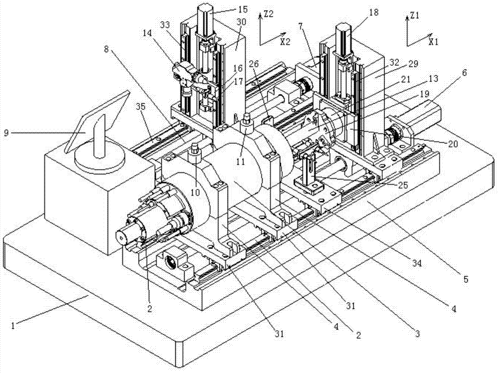
[0035] Such asfigure 1 As shown, the present invention provides an intelligent dynamic balancing device for a high-speed spindle machine, which includes a bottom plate 1 and is characterized in that it also includes a fixed connection part of the spindle system, an automatic rotor clamping and rotating part, a laser automatic Alignment and deduplication part, unbalance detection part;
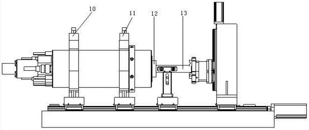
[0036] The fixed coupling part of the spindle system includes a high-speed spindle 3, a spindle positioning seat 4 for fixing the high-speed spindle 3, and a spindle area base 5; wherein the spindle positioning seat 4 and the spindle area base 5 fixed on the base plate 1 are fixed in the spindle area The X1 direction guide rail 2 on the base 5 is slidably connected, and the position of the spindle positioning seat 4 on the base 5 in the spindle area can be fixed; the structure diagram of the spindle area is shown in figure 2 shown.
[0037] see Figure 4 , the rotor automatic clamping and ro...
Embodiment 2
[0041] On the basis of Embodiment 1, the spindle positioning seat 4 is slidingly connected to the spindle area base 5 fixed on the bottom plate 1, and the position of the spindle positioning seat 4 on the spindle area base 5 can be fixed. The structure is: the main shaft positioning seat 4 is fixedly connected with the guide rail slider one 31, the guide rail slider one 31 is slidingly connected with the X1 direction guide rail 2, and the guide rail slider one 31 can be fixed on the X1 direction guide rail 2, specifically the guide rail slider one 31 is fixed between the pin and the X1 direction guide rail 2.
[0042] The Z1 direction workbench 20 is slidably connected along the Z1 direction on the Z1 direction base 29 and can automatically adjust the position of the Z1 direction workbench 20 on the Z1 direction base 29. The specific structure is: the Z1 direction workbench 20 and The bases 29 in the Z1 direction are slidingly connected by the guide rail 32 in the Z1 direction...
PUM
 Abstract
Description
Claims
Application Information
 - R&D
- Intellectual Property
- Life Sciences
- Materials
- Tech Scout
- Unparalleled Data Quality
- Higher Quality Content
- 60% Fewer Hallucinations
Browse by: Latest US Patents, China's latest patents, Technical Efficacy Thesaurus, Application Domain, Technology Topic, Popular Technical Reports.
© 2025 PatSnap. All rights reserved.Legal|Privacy policy|Modern Slavery Act Transparency Statement|Sitemap|About US| Contact US: help@patsnap.com


