Magnetic leakage corrosion track detector for inner wall of pipeline

A magnetic flux leakage detection and detector technology, applied in pipeline systems, instruments, measuring devices, etc., can solve problems such as difficult speed control, increased counting error, mileage wheel slippage, etc., and achieves compact structure, strong coupling ability, and reliability and effectiveness strongly supported by the effect

Inactive Publication Date: 2015-07-08
SHENYANG ACAD OF INSTR SCI +1
View PDF7 Cites 12 Cited by
  • Summary
  • Abstract
  • Description
  • Claims
  • Application Information

AI Technical Summary

Problems solved by technology

[0008] The traditional mileage wheel joint adopts the method of uniformly distributing three mileage wheels in the circumferential direction. The reason for arranging three mileage wheels is that the detector travels in the pipeline at a speed of 0.5 m / s to 5 m / s, and is affected by the flow fluctuation of the medium, and The ups and downs of the pipeline make it difficult to control the speed, so the mileage wheel will cause slippage, resulting in counting errors. In order to eliminate this error, three mileage wheels are installed, and the average value of the three mileage wheel rotations is used as the expected value
However, in the DN219 pipeline, due to the narrow space, if the method of arranging three mileage wheels in the circumferential direction is still adopted, the diameter of the mileage wheel must be reduced. The smaller the diameter of the mileage wheel, the more obvious the slipping phenomenon, resulting in a significant increase in the counting error

Method used


Image

  • Magnetic leakage corrosion track detector for inner wall of pipeline
  • Magnetic leakage corrosion track detector for inner wall of pipeline
  • Magnetic leakage corrosion track detector for inner wall of pipeline

Examples


Embodiment Construction

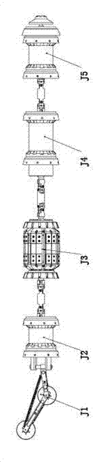
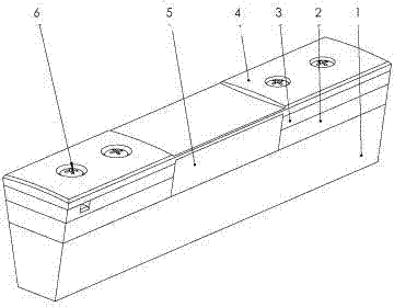
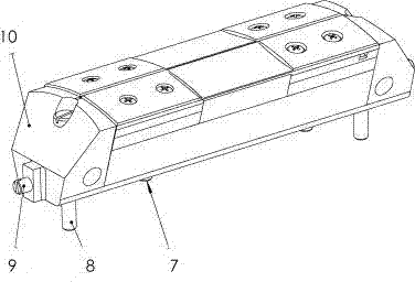
[0028] according to Figure 1 to Figure 7 The present invention is described in detail. The battery section J5, the computer section J4, the magnetic flux leakage detection probe section J3, the positioning section J2, and the mileage wheel section J1 described in the figure are arranged in sequence, and the adjacent two sections are connected by a positioning coupling; the magnetic flux leakage detection probe Section J3 includes a magnetic flux leakage section skeleton 11 arranged axially and with mounting flanges at both ends. Probe brackets 10 are evenly distributed along the circumference between the two ends of the flanges, and an integrated probe is arranged in the probe bracket 10; The two ends of each probe bracket are provided with an upper limit post 9 that can slide in the flange groove on the magnetic flux leakage joint skeleton 11, and the bottom of the two ends of the probe bracket is also provided with a sliding up and down in the corresponding hole on the magn...


PUM


Abstract

The invention discloses a magnetic leakage corrosion track detector for the inner wall of a pipeline, comprising a battery section, a computer section, a magnetic leakage detection probe section, a location section and an odometer wheel section. The detector is technically characterized in that the magnetic leakage detection probe section comprises an axial magnetic leakage section skeleton with mounting flanges at two ends, a probe bracket is evenly distributed in circumferential direction between the mounting flanges at two ends, and an integrated probe is arranged in the probe bracket; the integrated probe structurally comprises two probes arranged in parallel, each probe is formed by that two sides of the upper part of a strip-shaped yoke are respectively provided with a pair of magnets with opposite polarity, each magnet is orderly provided with an iron liner, a wear-resistant body and a stainless steel substrate spray-welding tungsten carbide hard coating upwards, a sensor box is arranged at the upper middle part of each strip-shaped yoke, and a sensor is cast in each sensor box; the odometer wheel section is of a self-coupling swinging arm type odometer wheel structure, through holes are evenly distributed in circumferential direction of an odometer wheel, an inductive transducer is mounted on a rotating arm, and the induction end of the inductive transducer straightly faces towards the circumferential through holes of the odometer wheel. The structure is particularly suitable for a magnetic leakage detector of a DN219 small-diameter pipeline.

Description

technical field [0001] The invention belongs to the technical field of pipeline detection, in particular to a pipeline inner wall magnetic flux leakage corrosion diameter detector mainly used for long-distance pipelines. Background technique [0002] Pipeline transportation capacity represents a country's industrial development level. Domestic pipeline laying is currently developing at a rate of 10,000 to 20,000 kilometers per year. By 2015, the total length of my country's oil and gas pipelines will reach 140,000 kilometers. [0003] Oil and gas pipelines are oil and gas transmission facilities, and their safety performance is very important. Long-term operation of oil and gas pipelines will cause failure due to corrosion, mechanical damage, geological damage, and pipe defects. In severe cases, it will cause fire, explosion, and poisoning, affecting the surrounding environment and the lives of the people. At the same time, it will cause a great waste of energy transmission....

Claims


Application Information

Patent Timeline
IPC IPC(8): G01N27/90F17D5/00G01N27/9093
Inventor 宋华东王晓凡赵晓利汪刚蒋兴桥杨路郭晓婷马洪发张振洲韩乃波马岩
Owner SHENYANG ACAD OF INSTR SCI
Why Eureka
Try Eureka