Oil nozzle abrasive flow machining particle movement numerical simulation method

A technology of numerical simulation and particle movement, applied in the direction of electrical digital data processing, special data processing applications, instruments, etc., can solve problems such as difficult to meet processing requirements, and achieve a good guiding effect

Inactive Publication Date: 2015-07-08
CHANGCHUN UNIV OF SCI & TECH
View PDF4 Cites 14 Cited by
  • Summary
  • Abstract
  • Description
  • Claims
  • Application Information

AI Technical Summary

Problems solved by technology

Faced with these complex cavity parts with small size and high precision requirements, traditional processing methods are difficult to meet the processing requirements, and abrasive flow processing technology has emerged as the times require.

Method used


Image

  • Oil nozzle abrasive flow machining particle movement numerical simulation method

Examples


Embodiment

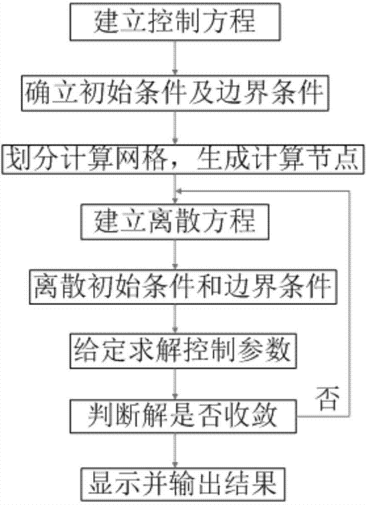
[0023] like figure 1 As shown, the embodiment of the present invention takes the fuel injector as the object, and the specific steps for numerical simulation are as follows:

[0024] (1) Establish a calculation model: the selected fuel injector part is a fuel injector part of a diesel engine, and six small nozzle holes are evenly distributed at its end, the diameter of the large hole in the flow path is 4mm, and the diameter of the small hole is 0.16mm. 3D solid model drawn by Soildworks software. In order to facilitate the simulation analysis, the drawn three-dimensional solid diagram of the fuel injector is simplified, its solid part is hidden, and its internal channel part is abstracted, only the main channel of the fuel injector and the six nozzle channels are reserved.

[0025] (2) Set the solution parameters: Before the simulation, the characteristic parameters, initial parameters, and boundary conditions of the abrasive flow should be set, as follows:

[0026] (2a) In...


PUM


Abstract

The invention relates to an oil nozzle abrasive flow machining particle movement numerical simulation method. The method includes the specific steps that 1, a computation model is built; 2, solution parameters are set, wherein before simulation, feather parameters, initial parameters, boundary conditions and the like of abrasive flow are set; 3, a model grid and areas are divided; 4, a solver is set and solution computation is conducted; 5, a calculation result is after-processed, wherein a particle track is displayed, a position distribution graph of particles is displayed, and a particle speed vector diagram is displayed. By means of the method, numerical simulation is conducted on a discrete particle phase in a flow field for oil nozzle abrasive flow machining, coupling of discrete-phase particles and continuous-phase fluid is computed, movement data of the discrete particles are obtained, and it draws a conclusion that the movement condition of the particles in the abrasive flow machining process is related to turbulence intensity of the fluid, the relation among non-linear pipe channel surface quality, the particles and wall face collisions is discussed, and a good guide function is performed.

Description

technical field [0001] The invention relates to a numerical simulation method for particle movement in abrasive flow processing of fuel injectors, and belongs to the technical field of abrasive flow processing simulation. Background technique [0002] At present, with the continuous development of the manufacturing industry, the precision requirements for parts in various fields are also continuously increasing. Especially in the fields of aerospace, automobile manufacturing, medicine and military industry, there are high precision requirements for parts. For example, common rail pipes, fuel injector parts, and valve cores widely used in aviation vehicles, which are important components in automobile fuel supply systems, all have high requirements on surface quality. Faced with these complex cavity parts with small size and high precision requirements, traditional processing methods are difficult to meet the processing requirements, and abrasive flow processing technology h...

Claims


Application Information

Patent Timeline
Patent Type & Authority Applications(China)
IPC IPC(8): G06F17/50
Inventor 李俊烨吴桂玲侯吉坤张心明许颖刘建河孙凤雨
Owner CHANGCHUN UNIV OF SCI & TECH
Why Eureka
Try Eureka