Vibration detector
A technology of detectors and vibration switches, applied in the direction of burglar alarm mechanical start, etc., to reduce false alarms and improve performance
- Summary
- Abstract
- Description
- Claims
- Application Information
AI Technical Summary
Problems solved by technology
Method used
Image
Examples
Embodiment 1
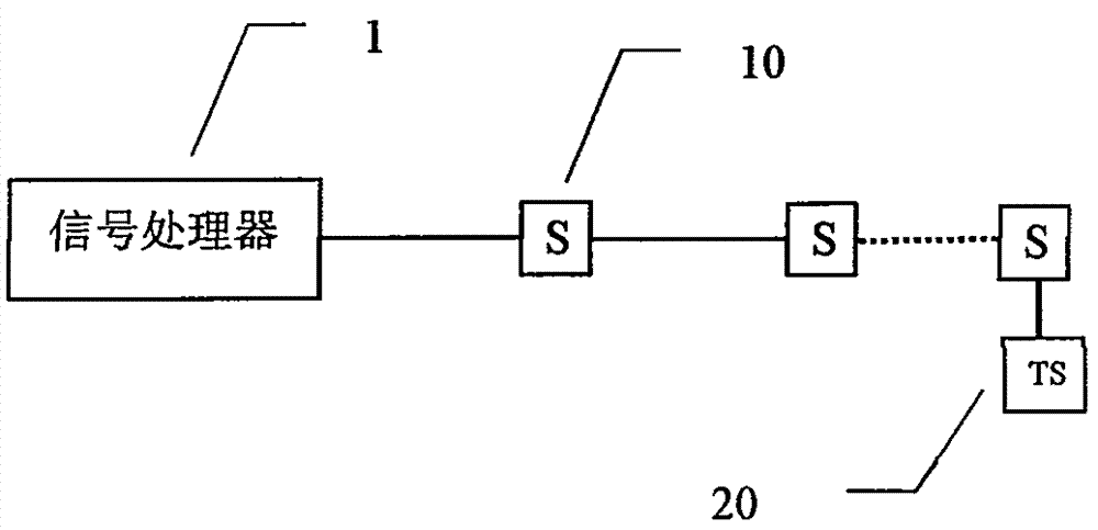
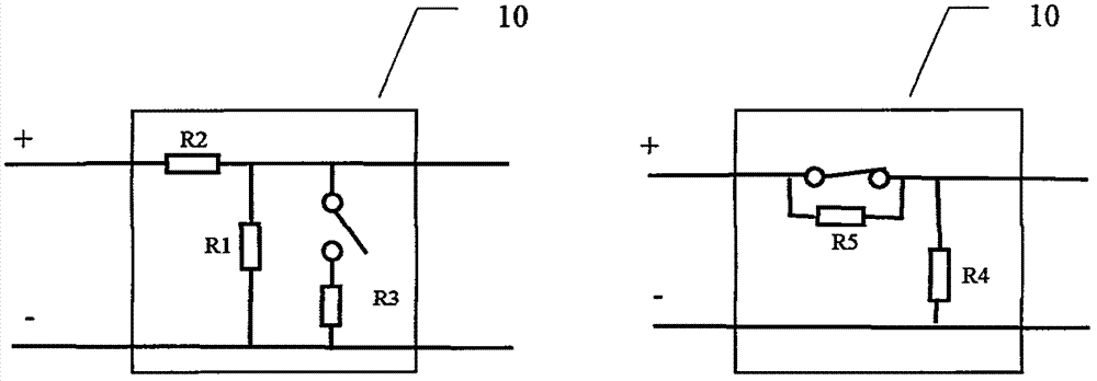
[0018] Example 1, such as figure 2 In the normally open sensing module 10, the resistors R2 and R3 are both short-circuited, and only the resistor R1 and the normally open switch are connected in parallel in the circuit. When a large vibration occurs, the specific resistance of the module changes to a "0" resistor, then The processor can collect corresponding voltage drop signals or high and low level signals. If this circuit is used, multiple sensing modules can be directly connected in series, and figure 1 The structure of the end sensing module 20 shown can be exactly the same as that of the middle sensing module 10 . For this detector, when the switch of any module is closed, the same circuit effect will be produced (change from a specific resistance value to "0" resistance value, and the resistance value of the connecting cable and each welding point is ignored here). For the induction module of this structure, if multiple modules are closed at the same time, the effec...
Embodiment 2
[0019] Example 2, such as figure 2 In the normally open sensing module 10, the resistor R1 is disconnected, and R2 and R3 are 0, that is, only a normally open switch is connected to the positive and negative wires in the circuit. In this way, when the switch of one or more sensing modules of the detector is closed, the resistance value of the circuit changes from infinity to "0". One drawback of this design is that if the cable between the detectors is cut, the detectors fail. Therefore, the terminal sensing module 20 should be adjusted. A simple way is to parallel a resistor on the switch, then the system has three states: short circuit when vibrating, specific resistance value when normal, and open circuit when the cable is cut. Similarly, in this embodiment, it is also impossible to judge which module is giving an alarm, and it is also difficult to judge the situation that multiple modules are giving an alarm at the same time.
[0020] In the above two embodiments, the s...
Embodiment 3
[0021] Example 3, such as figure 2 In the normally open sensing module 10 shown, the resistor R1 is disconnected, and R2 and R3 select specific resistance values, for example, both are 1000 ohms. For a multi-point detector with multiple sensing modules of this structure connected in series, the circuit resistance generated by the action of each module will be significantly different, and the results of multiple sensing modules acting at the same time will also be different, so it can be judged that Which sensors generate action. The terminal sensing module 20 of this embodiment may adopt the same circuit structure as the sensing module 10, or may adopt a different structure, such as optimizing R1, R2, and R3 according to the cable impedance characteristics.
[0022] For Embodiment 3, the signal processor can only make a judgment on the sensing position if it collects the voltage value signal.
[0023] For the sensing module 10 adopting a normally closed switch, the switch i...
PUM
 Abstract
Description
Claims
Application Information
 - R&D
- Intellectual Property
- Life Sciences
- Materials
- Tech Scout
- Unparalleled Data Quality
- Higher Quality Content
- 60% Fewer Hallucinations
Browse by: Latest US Patents, China's latest patents, Technical Efficacy Thesaurus, Application Domain, Technology Topic, Popular Technical Reports.
© 2025 PatSnap. All rights reserved.Legal|Privacy policy|Modern Slavery Act Transparency Statement|Sitemap|About US| Contact US: help@patsnap.com


