Method and circuit arrangement for determining a working range of an ultrasonic vibrating unit

A technology of vibration mechanism and working range, which is applied in the direction of using vibration fluid, measuring electricity, manufacturing tools, etc., and can solve the problems of operator danger, inability to work, high sound intensity, etc.

Active Publication Date: 2015-07-08
WEBER ULTRASONICS
View PDF4 Cites 4 Cited by
  • Summary
  • Abstract
  • Description
  • Claims
  • Application Information

AI Technical Summary

Problems solved by technology

However, the emission of sound waves in idling on the one hand causes very high sound intensities and on the other hand damages the vi

Method used


Image

  • Method and circuit arrangement for determining a working range of an ultrasonic vibrating unit
  • Method and circuit arrangement for determining a working range of an ultrasonic vibrating unit
  • Method and circuit arrangement for determining a working range of an ultrasonic vibrating unit

Examples


Embodiment Construction

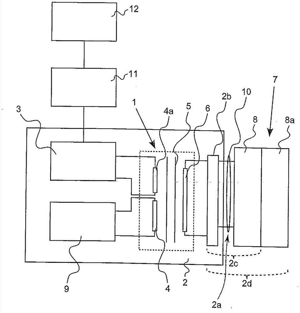
[0032] figure 1 The equivalent circuit diagram of an ultrasonic vibration system is shown in FIG. 1 , which according to one embodiment of the invention has a transformer 1 (dashed box) which is arranged inside a (ultrasonic) generator 2 . This transformer 1 is also connected to a measuring circuit 3 . The primary-side transformer winding 4 is operatively connected via a ferrite core 5 to an inductance (secondary-side transformer winding) 6 , wherein the transformer 1 also has an additional primary-side auxiliary winding 4a in the exemplary embodiment shown. .

[0033] The inductance 6 is electrically connected on the secondary side of the transformer 1 to an ultrasonic transducer 8 which is connected by means of a cable 10 to the output 2 a of the generator 2 and is connected to the usual presence of the inductance 6 and the generator 2 The matching network 2b together forms an electrical resonant circuit 2c. The ultrasonic transducer 8 , for example a piezo transducer, co...


PUM


Abstract

The invention relates to a method for determining a working range of an ultrasonic vibrating unit (7), which ultrasonic vibrating unit (7) is supplied with electrical power by a generator (2) via an output (2a) and is excited to vibrate ultrasonically, wherein at least constituent parts of the ultrasonic vibrating unit (7), preferably an ultrasonic converter (8) contained therein, and constituent parts of the generator (2), preferably a matching network (2b) on the output side, form a tuned circuit (2c, 2d). Said method is characterized in that a measuring circuit (3) is connected upstream of the output (2a) of the generator (2), via the measuring circuit (3), a voltage (U) is applied to the tuned circuit, by means of the measuring circuit (3), at least the phase, preferably magnitude and phase, of an impedance of the tuned circuit are measured, and at least the phase, preferably the phase and magnitude, of the impedance are evaluated in order to determine the working range. The invention further relates to a circuit arrangement for carrying out the aforementioned method.

Description

technical field [0001] The invention relates to a method according to the preamble of claim 1 for determining the operating range of an ultrasonic-oscillating mechanism supplied with electrical energy via an output by a generator and excited to cause ultrasonic vibrations , wherein at least the components of the ultrasonic vibration mechanism, preferably the ultrasonic transducer contained in the ultrasonic vibration mechanism, and the components of the generator, preferably a matching network on the output side, form a resonant circuit. [0002] The invention also relates to a circuit arrangement according to the preamble of claim 8 for carrying out the method according to the invention, which circuit arrangement has an ultrasonic vibration mechanism which is connected to a generator And can be supplied with electric energy by this generator through the output end and can be excited to cause ultrasonic vibration, wherein, at least by the assembly of ultrasonic-vibration mecha...

Claims


Application Information

Patent Timeline
IPC IPC(8): B06B1/02
CPCB06B1/0261B23K20/10B06B2201/40G01R31/2829B06B1/0207G01R27/02
Inventor X·布鲁恩R·布罗斯蔡特
Owner WEBER ULTRASONICS
Why Eureka
Try Eureka