Refine method of hot metal

A technology for molten iron and refining furnaces, which is used in the improvement of process efficiency, manufacturing converters, metal recovery, etc., can solve the problems of bump boiling, reduction in production volume, and increase in loss of refractory materials in the furnace body, so as to increase the compounding amount and the yield of finished products. improved effect

Active Publication Date: 2015-07-08
JFE STEEL CORP
View PDF5 Cites 3 Cited by
  • Summary
  • Abstract
  • Description
  • Claims
  • Application Information

AI Technical Summary

Problems solved by technology

[0012] That is, in Patent Document 1, since the slag remaining in the decarburization refining furnace is temporarily recovered and used after crushing, the heat possessed by the slag is not recovered.
In addition, when the slag is discharged from the decarburization refining furnace, the molten steel remaining in the decarburization refining furnace is discharged out of the refining process system together with the slag and processed, so it becomes a factor of deterioration of the molten steel yield
[0013] In Patent Document 2, it is necessary to arrange the molten iron holding container for storing the molten iron directly below the decarburization refining furnace in the vertical direction, which may not be possible due to the height restriction directly below the furnace.
In addition, even if it can be implemented, because the molten iron holding container is arranged directly under the decarburization refining furnace, or the molten iron holding container after receiving the slag is moved to the dephosphorization refining furnace, the molten iron is kept from the molten iron. The container is loaded into the dephosphorization refining furnace, etc., so the molten iron holding container is frequently and cumbersomely moved, which is easy to cause time loss, resulting in a decrease in production volume and a decrease in the temperature of the molten iron
In addition, if the slag discharged to the molten iron holding container and the undeoxidized molten steel are involved in the molten iron, there is a danger of sudden CO gas generation and bumping, which also poses a safety problem.
[0014] In Patent Document 3, the process from dephosphoriz

Method used


Image

  • Refine method of hot metal
  • Refine method of hot metal

Examples


Example Embodiment

[0062] Example

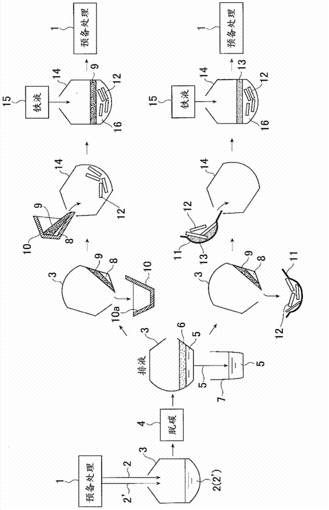
[0063] Hereinafter, the present invention will be described in further detail through examples. according to figure 1 In the shown processing flow of the molten iron refining method of the present invention, the following tests were performed. In the following test, the dephosphorization treatment (desiliconization / dephosphorization treatment) of the molten iron that was not subjected to the desiliconization treatment in the preliminary treatment refining furnace 14 was performed.

[0064] The low-phosphorus molten iron 2 with a phosphorus concentration of 0.020% by mass is charged into a 300-ton capacity decarburization refining furnace 3 (converter), and quicklime and dolomite are charged as fluxes. Argon gas (Ar Gas) is blown in as a stirring gas and oxygen is supplied from the top blowing lance to perform decarburization refining. After the decarburization refining is completed, the obtained molten steel 5 is discharged to the ladle 7, and the molten steel 5...


PUM


Abstract

When manufacturing molten steel from hot metal using a two base converter-type refining furnace and using one as a hot metal pretreatment refining furnace and the other as a hot metal decarburization refining furnace, the molten slag generated in the decarburization refining furnace is used while still hot as a refining agent in the pretreatment refining furnace without compromising the productivities of the two refining furnaces. A refining method for manufacturing molten steel from hot metal using a converter-type refining furnace with at least two bases and using one as a hot metal pretreatment refining furnace (14) and using the other as a decarburization refining furnace (3) for the hot metal (2) pretreated in the pretreatment refining furnace. After the molten steel (5) obtained by decarburization refining in the decarburization refining furnace has been tapped in a ladle (7), the slag (9) remaining inside the decarburization refining furnace is allowed to flow down, still in the molten state, from above stacked iron scraps to solidify at least a portion of the slag. Then in pretreatment of hot metal in the pretreatment refining furnace, the slag, at least a portion of which has been solidified, is used together with the iron scraps while still hot.

Description

technical field [0001] The present invention relates to a method for refining molten iron, which uses at least two sets of converter-type refining furnaces, one of which is used as a hot metal pretreatment furnace for molten iron, and the other is used as a hot metal pretreatment furnace for pretreatment The final decarburization refining furnace of molten iron is used to smelt molten steel from molten iron. In detail, it relates to a refining method using slag generated in a decarburization refining furnace in a high-temperature state as a refining agent for a preliminary treatment refining furnace. Background technique [0002] Technological development to meet the demands for higher quality and lower prices of various steel materials is carried out in each process of the iron and steel manufacturing process. In the refining process of smelting molten steel from molten iron, the impurity components transferred / separated from the molten metal phase to the slag phase by ref...

Claims


Application Information

Patent Timeline
IPC IPC(8): C21C1/02C21C5/28
CPCC21C5/562C21C1/02Y02W30/54C21C5/28Y02P10/20
Inventor 前田孝彦川畑凉田中高太郎山本和人石毛俊朗小泽纯仁泷口满章古家雅之
Owner JFE STEEL CORP
Why Eureka
Try Eureka