Air flowing bed

An air flow, bed body technology, applied in the direction of hospital beds, medical science, hospital equipment, etc., can solve the problems of reducing the patient's treatment effect, the filtering effect is not very good, and increasing the cost of use, so as to reduce the manufacturing cost and facilitate maintenance. The effect of reducing maintenance and production difficulty

Inactive Publication Date: 2015-07-15
NINGBO YILONG MEDICAL EQUIP
View PDF10 Cites 2 Cited by
  • Summary
  • Abstract
  • Description
  • Claims
  • Application Information

AI Technical Summary

Problems solved by technology

[0003] The air fluidized bed currently in use is to fix the filter sheet around the fluidization chamber, and then place an ordinary bed sheet on the filter sheet, and the patient lies on the bed sheet, but the effect of fixing the filter sheet in the fluidization chamber is not very good, often occurs The microparticles in the fluidization chamber escape from the gap between the filter sheet and the fluidization chamber, especially in the arc edge area of ​​the fluidization chamber. The escape phenomenon is particularly serious, resulting in the loss of microparticles, which increases the use cost and reduces therapeutic effect on patients

Method used


Image

  • Air flowing bed
  • Air flowing bed
  • Air flowing bed

Examples


Embodiment Construction

[0022] The present invention will be further described below in conjunction with the accompanying drawings and embodiments.

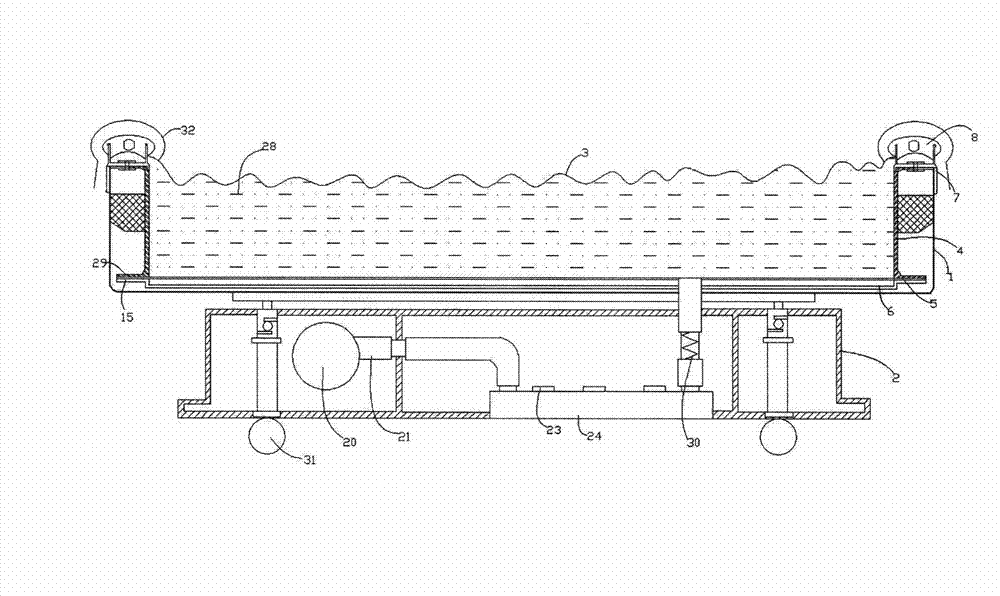
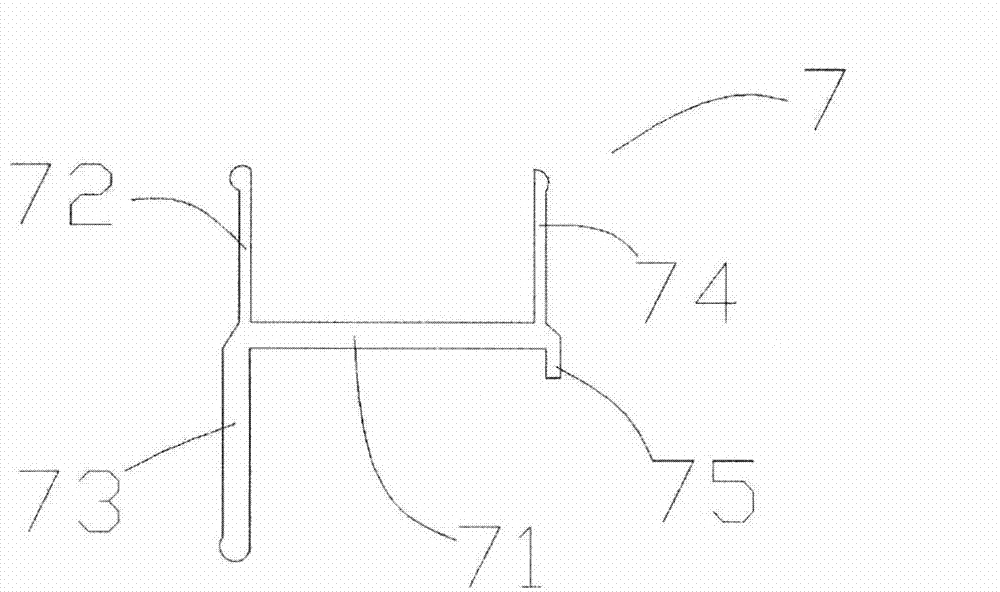
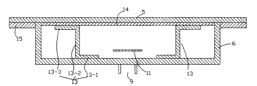
[0023] Such as figure 1 , 2 As shown, an air flow bed provided by the present invention includes an upper bed body 1 and a lower bed body 2, the upper bed body 1 is erected on the lower bed body 2, and filter sheets are sequentially arranged in the upper bed body 1 from top to bottom 3. The fluidized cabin 4, the breathable plate 5 and the hyperbaric cabin 6, the fluidized cabin 4 is filled with a sufficient amount of microparticles 28, and the lower bed body 2 is provided with a control system, an air intake system, a temperature control system and a scale Weight system, the air intake system, temperature control system and weighing system are electrically connected to the control system respectively, and also includes a frame 7, the frame is made of aluminum, and the frame 7 includes a base 71, the base The two ends of 71 extend up and down respecti...


PUM


Abstract

The invention discloses an air flowing bed. The air flowing bed comprises an upper bed body and a lower bed body, and further comprises a side frame, wherein a filter unit, a fluidization cabin, a permeable plate and a high-pressure cabin are arranged in the upper bed body from top to bottom in sequence; a control system as well as an air inlet system, a temperature control system and a weighing system which are electrically connected with the control system are arranged in the lower bed body; the side frame comprises a foundation bed, and further comprises an elastic pressure strip, the two ends of the foundation bed respectively extend up and down to form an upper clamping ring I, a lower clamping ring I, an upper clamping ring II and a lower clamping ring II; an upper clamping slot is formed by the upper clamping ring I, the upper clamping ring II and the foundation bed; a lower clamping slot is formed by the lower clamping ring I, the lower clamping ring II and the foundation bed; the fluidization cabin and the upper bed body are clamped by the lower clamping slot; a thread gluing ring belt is arranged at one side of the upper clamping ring II; the filter unit is bonded with the thread gluing ring belt; the elastic pressure strip is embedded into the upper clamping slot and used for tightly pressing the periphery of the filter unit between the upper clamping slot and the elastic pressure strip. According to the air flowing bed disclosed by the invention, the air flowing bed has the technical effects that the thread gluing ring belt is arranged on the upper clamping ring II, the filter unit is fixed by the elastic pressure strip, micro particles in the fluidization cabin are not prone to run off, and a patient is enabled to be treated under a clean environment.

Description

technical field [0001] The present invention relates to an air fluidized bed. Background technique [0002] Air flow bed is a new type of medical bed, which is widely used in many fields of medicine. Its appearance is like a large bathtub. Instead of water, it is filled with very fine particles to form a bed of particles. The filling height of the particles is about 30 cm. The particles are composed of silicon and ceramics. The diameter of each particle is only 50- 150 microns. An air-permeable perforated plate is placed under the granules, and the perforated plate distributes the compressed air evenly. When filtered compressed air flows up through the fine particles, the particles flow like water, creating considerable buoyancy enough to keep the patient afloat on top of the flowing particles. When the patient floats on the flowing particles, the contact area between the human body and the particles is quite large, but the pressure per unit contact area is very small, be...

Claims


Application Information

Patent Timeline
Patent Type & Authority Applications(China)
IPC IPC(8): A61G7/00A61G7/05
Inventor 卢北众潘丽芳俞光良
Owner NINGBO YILONG MEDICAL EQUIP
Why Eureka
Try Eureka