Wind-solar electricity generation system used on expressway

A technology for wind power generation and highways, applied in photovoltaic power generation, wind power generation, photovoltaic power stations, etc., can solve the problem that power generation equipment cannot provide power frequency AC 220V and 380V, cannot meet road traffic control information equipment, and difficult equipment can provide stable and continuous power and other issues, to achieve the effect of convenient installation, long life and energy saving

Inactive Publication Date: 2015-07-15
SUZHOU CHANGSHI IND EQUIP
7 Cites 3 Cited by

AI-Extracted Technical Summary

Problems solved by technology

However, as we all know, the wind resources on the expressway are discontinuous, and it is difficult to provide stable and continuous power for equipment
Moreover, among the wind power generation ...

Method used

Diode D8 is anti-reverse diode, to guarantee the one-way conductivity of solar photovoltaic array 3, has avoided blower fan 1 rectification voltage and the impact of storage battery on solar photovoltaic array 3 simultaneously. The addition of diode D7 and fuse F1 has prevented storage battery The reverse connection of the battery, that is, when the battery is reversed, a short-circuit circuit is formed through the diode D7, and the excessive short-circuit current causes the fuse F1 to blow quickly and cut off the circuit, thereby protecting other components.
[0029] The wind power generation system designed in this embodiment is composed of solar photovoltaic array 3, blower fan 1, permanent magnet generator 2, electric wire, power grid and load etc. The working mode is that ...

Abstract

The invention discloses a wind-solar electricity generation system used on an expressway. The wind-solar electricity generation system is composed of a solar photovoltaic array, a wind turbine, a permanent magnet generator, an electric wire, a power grid, a load and the like. When sunlight shines on the solar photovoltaic array, the solar photovoltaic array converts light energy into electric energy so as to generate electricity; when vehicles running on the expressway pass through isolation zones, wind power is generated to drive the generator to generate electricity. According to the working mode, the permanent magnet generator outputs an alternating current, the alternating current becomes a direct current after being rectified, and the direct current from the permanent magnet generator and a direct current from the photovoltaic array charge a storage battery under the control of a controller. The controller not only controls the permanent magnet generator and the solar photovoltaic array to charge the storage battery but also manages charging of the storage battery for the load. A variable speed and constant frequency control model is adopted for the wind-solar electricity generation system, the permanent magnet generator is adopted as an engine, and therefore stable and continuous electric energy can be provided, and power frequency alternating current 220V electric energy and power frequency alternating current 380V electric energy can be provided.

Application Domain

Batteries circuit arrangementsPV power plants +3

Technology Topic

Control modePower grid +16

Image

  • Wind-solar electricity generation system used on expressway
  • Wind-solar electricity generation system used on expressway

Examples

  • Experimental program(1)

Example Embodiment

[0020] The present invention will be further described below in conjunction with the drawings and embodiments.
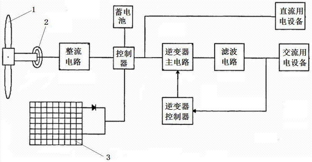
[0021] Such as Figure 1 to Figure 2 As shown, it is a wind and solar power generation system for highways according to the present invention, which includes a solar photovoltaic array 3, a wind turbine 1, a permanent magnet generator 2, an electric wire, and a power grid.
[0022] Wherein, the solar photovoltaic array 3 and the fan 1 are installed in two consecutive rows and tiling on the inner side of the guardrails on both sides of the isolation belt. The fan 1 is connected to the permanent magnet generator 2 and the permanent magnet generator The generators 2 are fixedly installed in two rows on the lower side of the solar photovoltaic array 3 near the lane, and the output ends of the solar photovoltaic array 3 and the permanent magnet generator 2 are connected to the power grid through wires.
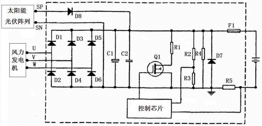
[0023] The power grid includes a rectifier circuit, a controller, an inverter controller, an inverter main circuit, and a filter circuit. The output end of the permanent magnet generator 2 is connected to the rectifier circuit through a wire. The output end of the solar photovoltaic array 3 is connected to the controller, and the controller sends the DC power to the battery, the DC power equipment and the inverter main circuit respectively, and the inverter main circuit passes through the filter After the circuit, the power frequency alternating current is sent to the alternating current electrical equipment and the inverter controller, and the output terminal of the inverter controller is connected to the inverter main circuit. The final output voltage is confirmed by the inverter controller according to the output current/voltage detection signal feedback, and controls the power frequency AC 220V or 380V voltage output.
[0024] When sunlight hits the solar photovoltaic array 3, the solar photovoltaic array 3 converts the light energy into electric energy to generate electricity. When a car driving on the highway passes along the side of the isolation belt, the generated wind drives the permanent magnet engine 2 to generate electricity. This kind of wind and solar power generation system used on highways is not only easy to install, but also has the advantages of long life, energy saving, and environmental protection. On the other hand, it also beautifies the landscape construction of the highway and forms a beautiful landscape.
[0025] Preferably, the circuit structure of the controller includes an electrolytic capacitor C1, a capacitor C2, a field effect tube Q1, a resistor R1, a resistor R2, a resistor R3, a resistor R4, a resistor R5, a fuse F1, a diode D7, a diode D8, and a control chip , The first input end of the solar photovoltaic array 3 is connected to the anode of the diode D8, and the cathode of the diode D8 is connected to the fuse F1; after the electrolytic capacitor C1 and the capacitor C2 are connected in parallel, one end is connected to the fuse F1, and the other end is connected to the field effect tube The source of Q1 is connected; the gate of the field effect tube Q1 is connected to the control chip, the drain of the field effect tube Q1 is connected to the resistor R1, the other end of the resistor R1 is connected to the fuse F1; the resistor R2 and the resistor R3 are connected in series with the resistor R4 is connected in parallel, one end of resistor R2 and resistor R4 is connected to fuse F1, one end of resistor R3 and resistor R4 is connected to resistor R5, the source of FET Q1 is connected to resistor R5, and the other end of resistor R5 is connected to the output of the control chip Both ends are connected to the negative electrode of the battery, and the positive electrode of the battery is connected to the fuse F1.
[0026] The diode D8 is an anti-reverse diode to ensure the unidirectional conductivity of the solar photovoltaic array 3, while avoiding the influence of the rectified voltage of the fan 1 and the battery on the solar photovoltaic array 3. The addition of the diode D7 and the fuse F1 prevents the reverse connection of the battery , That is, when the battery is reversely connected, a short-circuit circuit is formed by the diode D7, and the excessive short-circuit current causes the fuse F1 to quickly fuse and cut off the circuit, thereby protecting other components.
[0027] Preferably, the rectifier circuit includes a rectifier diode D1, a rectifier diode D2, a rectifier diode D3, a rectifier diode D4, a rectifier diode D5, and a rectifier diode D6, wherein the rectifier diode D1 is connected in series with the rectifier diode D2, and the rectifier diode D3 is connected in series with the rectifier diode D4. The rectifier diode D5 is connected in series with the rectifier diode D6; the first output terminal of the fan 1 is connected to the anode of the rectifier diode D1, the second output terminal of the fan 1 is connected to the anode of the rectifier diode D3, and the first output terminal of the fan 1 The three output terminals are connected with the anode of the rectifier diode D5; the cathode of the rectifier diode D1 is connected with the cathode of the rectifier diode D3 and the cathode of the rectifier diode D5, and the anode of the rectifier diode D2 is connected with the anode of the rectifier diode D4 and the anode of the rectifier diode D6.
[0028] Preferably, the control chip is an SG3525 voltage pulse width modulation chip.
[0029] The wind and solar power generation system designed in this embodiment for expressway is composed of a solar photovoltaic array 3, a wind turbine 1, a permanent magnet generator 2, a wire, a power grid, and a load. The working mode is that the permanent magnet generator 2 outputs alternating current, which is rectified into direct current, and at the same time, the direct current of the photovoltaic array is controlled by the controller to charge the battery. In addition to controlling the charging of the battery by the permanent magnet generator 2 and the solar photovoltaic array 3, the controller also includes the management of discharging the battery to the load. The wind and solar power generation system adopts a variable speed constant frequency control method, and the engine adopts a permanent magnet synchronous generator, which can not only provide stable and continuous electrical energy, but also provide two types of power frequency AC 220V and 380V.
[0030] An embodiment of the present invention has been described in detail above, but the content is only a preferred embodiment created by the present invention, and cannot be considered as limiting the scope of implementation of the present invention. Any equivalent changes made according to the scope of the application of the present invention should still be within the scope of the patent of the present invention.

PUM

no PUM

Description & Claims & Application Information

We can also present the details of the Description, Claims and Application information to help users get a comprehensive understanding of the technical details of the patent, such as background art, summary of invention, brief description of drawings, description of embodiments, and other original content. On the other hand, users can also determine the specific scope of protection of the technology through the list of claims; as well as understand the changes in the life cycle of the technology with the presentation of the patent timeline. Login to view more.

Similar technology patents

Scraper pan positioning device and method for backhoe excavator

ActiveCN103852059AEasy to installgood measurement
Owner:CHINESE NONFERROUS METAL SURVEY & DESIGN INSTITUE OF CHANGSHA

Fence and installation method thereof

Owner:ZHANGJIAGANG GOLDNET FENCING SYST

Classification and recommendation of technical efficacy words

  • extend your life
  • Easy to install

Light-emitting element

ActiveCN103081155AImprove quantum efficiencyextend your life
Owner:SEMICON ENERGY LAB CO LTD

Method, system and device for controlling vehicle power device and storage medium

ActiveCN108394401AAvoid violent dynamic load changesextend your life
Owner:TSINGHUA UNIV

Packaging method for white light illuminating diode

InactiveCN101068034AReduce light decay rateextend your life
Owner:NINGBO ANDY OPTOELECTRONIC CO LTD

Metal drawing oil

InactiveCN103031189Areduce heatextend your life
Owner:LOCKS LUBE SHANGHAI

Cooking electric appliance

PendingCN107647763AEasy to installAvoid insulation loss
Owner:FOSHAN SHUNDE MIDEA ELECTRICAL HEATING APPLIANCES MFG CO LTD

System for monitoring vibration of rotating machinery rolling bearing in wireless mode

InactiveCN102053016Ameasurementanalysisdatareal-timeEasy to install
Owner:JIANGSU UNIV
Why Eureka
Try Eureka