Molded product having hollow structure and process for producing same

A molded body and hollow technology, which is applied to hollow objects, chemical instruments and methods, household appliances, etc., can solve the problems of disordered reinforcement fiber orientation, weak resistance to external forces, and weak strength, and achieve high reinforcement effect and light weight Sexuality, the effect of maintaining rigidity

Active Publication Date: 2015-07-15
TORAY IND INC
View PDF8 Cites 22 Cited by
  • Summary
  • Abstract
  • Description
  • Claims
  • Application Information

AI Technical Summary

Problems solved by technology

[0003] Patent Document 1 discloses a prepreg capable of obtaining isotropic molded products with excellent mechanical properties and complex shapes. Document 1 describes a general rib shape, but the molded product disclosed therein does not have a rib shape with excellent strength and rigidity, so it may become a molded product that has a defective part against external force
[0004] Patent Document 2 discloses a sandwich structure which has a lightweight core material (which is formed with a structure having voids), and fiber reinforcements (which are continuously reinforced) on both sides of the core material. fiber and matrix resin), this technology is considered to be useful in obtaining a thin-walled, lightweight, and highly rigid molded body, but this sandwich structure is a core material and a fiber reinforcement material that are bonded and integrated. The bonded surface becomes the interface between different materials, so it may become a molded product with a defect in the molded product
[0005] Patent Document 3 discloses a skin-integrated product composed of a skin layer and a fiber-reinforced resin layer, and it is considered that this technology is due to the presence of reinforcing fibers between the skin layer and the resin layer in which the reinforcing fibers are oriented three-dimensionally. Since the resin layer is oriented in the dimension direction, complex shapes such as ribs can be easily formed, and it is useful in reducing the influence of voids on the surface, but the fiber length of the reinforcing fibers present in the resin layer forming the ribs is very short and cannot Effectively reinforce ribs etc.
In addition, due to the molding process, the orientation of the reinforcing fibers may be disturbed, which may produce directions that are weak against external forces
[0006] Patent Document 4 discloses a method for manufacturing a reinforcing plate made of thermoplastic resin and having a structure having voids. It is considered that the reinforcing plate obtained by this manufacturing method is obtained by combining two The sheets are bonded and integrated, and thickening can be easily achieved. However, since it is only made of thermoplastic resin, the strength of the convex part is low. When a surface load is applied to the entire structure, it is considered that the original form cannot be maintained.
[0007] It is known that when a bending stress is applied to the molded articles of Patent Documents 2 to 4, a stress distribution is formed such that the stress becomes maximum from the central plane (neutral axis) to both surfaces, and it is considered that the above-mentioned bonded surfaces that may form defects, When the root of the rib with weak strength exists near the surface of the molded body, it will cause the mechanical properties of the molded body to decrease

Method used


Image

  • Molded product having hollow structure and process for producing same
  • Molded product having hollow structure and process for producing same
  • Molded product having hollow structure and process for producing same

Examples


Embodiment

[0141] Hereinafter, the present invention will be described in more detail by way of examples.

[0142]

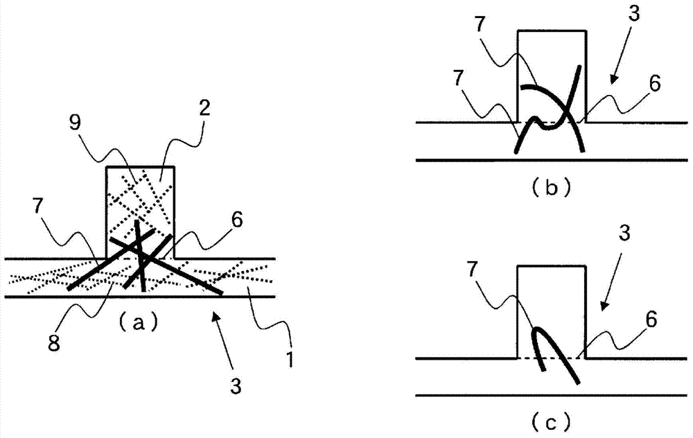
[0143] Cut out from the resulting molded body Figure 22 A portion having a protruding shape as shown in (a), such as Figure 22 As shown in (b), the surface layer portion having a planar shape was wet-polished to a position where the boundary surface between the surface layer portion and the core material portion could be observed, and this was used as a sample for cross-sectional observation. The entire cross-section of the polished sample was photographed at a magnification of 200 times using an ultra-depth color 3D shape measurement microscope VK-9500 (controller part) / VK-9510 (measurement part) (manufactured by KEYENCE Corporation). Measure every 1mm at any position of the boundary surface between the surface layer part and the core material part from the captured image using the analysis application VK-H1A9 2 The number of reinforcing fibers (a1).

[0144]

[...

reference example 1

[0184]

[0185] A continuous bundle of carbon fibers with a total of 12,000 filaments was obtained by spinning and firing a polymer mainly composed of polyacrylonitrile. A sizing agent was applied to the carbon fiber continuous bundle by a dipping method, and dried in heated air at a temperature of 120° C. to obtain a PAN-based carbon fiber bundle. The characteristics of this PAN-based carbon fiber bundle are as follows.

[0186] Single fiber diameter: 7μm

[0187] Weight per unit length: 0.83g / m

[0188] Density: 1.8g / cm 3

[0189] Tensile strength: 4.0GPa

[0190] Tensile modulus of elasticity: 235GPa

[0191] Type of sizing agent: polyoxyethylene oleyl ether

[0192] Sizing agent adhesion amount: 2% by weight

reference example 2

[0193]

[0194] The carbon fibers of Reference Example 1 were cut using a cartridge cutter to obtain chopped carbon fiber bundles having a fiber length of 3 mm.


PUM

PropertyMeasurementUnit
thicknessaaaaaaaaaa
lengthaaaaaaaaaa
heightaaaaaaaaaa

Abstract

A molded product obtained by unifying a first member (I) which is composed of both a plane surface layer part and a protruding core part and a second member (II), wherein: the first member (I) is made of a fiber-reinforced resin (A) which comprises reinforcing fibers (a1) and a matrix resin (a2); the reinforcing fibers (a1) extend across the boundary surface between the surface layer part and the core part: the quantity of reinforcing fibers (a1) extending across the boundary surface is 400 fibers / mm2 or more as observed at the boundary surface; the number-average fiber length (Ln) of the reinforcing fibers (a1) is 1mm or longer; and the core part constitutes a hollow structure. Thus, a molded product and a unified molded product which exhibit satisfactory lightness and meet the rigidity required in the market can be obtained.

Description

technical field [0001] The present invention relates to a molded body using a fiber-reinforced resin having a hollow structure. Background technique [0002] Sandwich structures or hollow structures using fiber-reinforced resin (FRP) are widely used in building structures such as transportation equipment such as aircraft and automobiles, as well as seismic reinforcement materials, as structures that have improved lightness while ensuring mechanical properties In recent years, personal computers and other electrical and electronic equipment casings that require thinner walls are used in various applications. [0003] Patent Document 1 discloses a prepreg capable of obtaining isotropic molded products with excellent mechanical properties and complex shapes. Document 1 describes a general rib shape, but the molded article disclosed therein does not have a rib shape excellent in strength and rigidity, and thus may be a molded article having a defective portion against external ...

Claims


Application Information

Patent Timeline
Patent Type & Authority Applications(China)
IPC IPC(8): B29C70/10B29C43/34B29C70/06B32B3/30B32B5/28C08J5/04B29K101/12B29K105/08
CPCB29L2031/608B29C43/34B29C43/02B29L2031/3481B29K2105/12B29D99/0089B29C70/081B32B5/28B32B3/30B29C70/202B32B5/022B32B5/024B32B5/026B32B5/08B32B27/12B32B27/20B32B27/22B32B27/285B32B27/32B32B27/34B32B27/36B32B27/365B32B27/42B32B2260/021B32B2262/0253B32B2262/0269B32B2262/101B32B2262/105B32B2307/3065B32B2307/558B32B2307/714B32B2307/7145B32B2307/734B32B2419/00B32B2457/00B32B2605/00B32B5/00B32B5/02B32B5/06B32B5/10B32B5/12B32B5/14B32B7/00B32B7/04B32B7/10B32B19/00B32B19/02B32B19/04B32B19/06B32B27/00B32B27/04B32B27/06B32B27/28B32B27/286B32B3/00B32B3/14B32B3/20B32B3/26B32B3/28B32B2262/00B32B2307/546B32B2307/718B32B2307/732B32B2535/00B32B2605/08B32B2605/18B32B2250/00Y10T428/24149Y10T428/24165B32B3/12B32B27/08B32B2262/106B29C43/021B29L2022/007B32B2305/08
Inventor 藤冈圣土谷敦岐
Owner TORAY IND INC
Why Eureka
Try Eureka