Cu-Nb composite wire straightening device

A composite wire, cu-nb technology, applied in the field of Cu-Nb composite wire straightening device, can solve the problem of unfavorable Cu-Nb composite wire straightening, affecting the performance of Cu-Nb composite wire, and unsuitable for Cu-Nb composite wire straightening and other problems, to achieve the effect of being suitable for mass production, improving straightness and stability, and high straightening efficiency

Active Publication Date: 2015-07-22
NORTHWEST INSTITUTE FOR NON-FERROUS METAL RESEARCH
View PDF6 Cites 6 Cited by
  • Summary
  • Abstract
  • Description
  • Claims
  • Application Information

AI Technical Summary

Problems solved by technology

There are many straightening devices related to metal wires, but they are not suitable for straightening Cu-Nb composite wires, mainly in the following aspects: (1) There is no wire traction mechanism, and the straightened wires pass through straightening rollers Transporting it out is not conducive to the straightening of Cu-Nb composite wire rods, the straightening effect is not good, and the straightening efficiency is low; (2) the wire rods are straightened by using straightening rollers, and the straightening rollers are not straightened after a period of use. When the straightening accuracy cannot meet the requirements, the straightening roller needs to be replaced as a whole, and the cost is high; (3) The straightening roller is made of bearing steel. During the straightening process, due to the different softness and hardness of different straightening wires, it will cause Cu -Nb composite wire peels off, which seriously affects the performance of Cu-Nb composite wire; (4) The tension device used is complex in structure, complicated in operation, and high in use cost

Method used


Image

  • Cu-Nb composite wire straightening device
  • Cu-Nb composite wire straightening device
  • Cu-Nb composite wire straightening device

Examples


Embodiment Construction

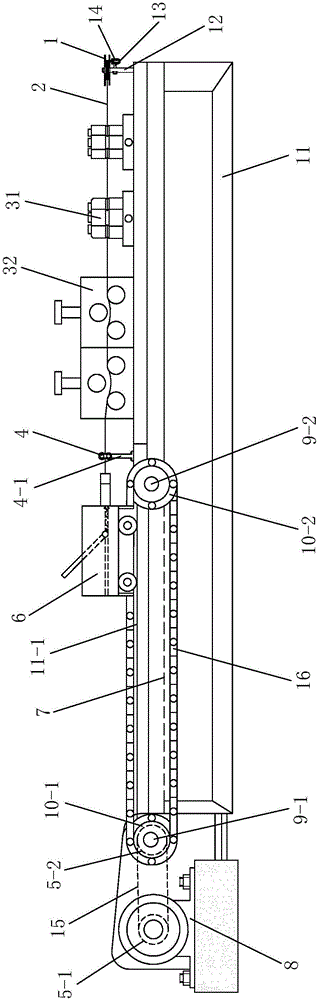
[0047] Such as figure 1 As shown, the present invention comprises a frame 11, on which a pay-off wheel 1, a first straightening unit 31, a second straightening unit 32, a guide wheel 4 and a wire rod for pulling Cu-Nb composite wire are installed in sequence on the said frame 11. 2 traction trolley 6, the Cu-Nb composite wire 2 is wound on the guide wheel 4, the pay-off wheel 1 is rotated and installed on the upper end of the pay-off reel shaft 12, and the lower end of the pay-off reel shaft 12 is fixed on the machine On the frame 11, the tension device 14 whose end is in contact with the lower end surface of the pay-off wheel 1 and prevents the Cu-Nb composite wire 2 from falling off is fixed on the pay-off reel shaft 12, the first straightening unit 31 and the second straightening unit 31 The straightening unit 32 has the same structure, the first straightening unit 31 is installed horizontally, the second straightening unit 32 is vertically installed, the guide wheel 4 is i...


PUM

PropertyMeasurementUnit
tensile strengthaaaaaaaaaa

Abstract

The invention discloses a Cu-Nb composite wire straightening device which comprises a rack. A paying-off wheel, a first straightening unit, a second straightening unit, a guide wheel and a trailer wagon are installed on the rack in sequence. The paying-off wheel is rotationally installed at the upper end of a paying-off spool shaft. The lower end of the paying-off spool shaft is fixed to the rack. A tension device is fixed to the paying-off spool shaft, wherein the end of the tension device makes contact with the lower end face of the paying-off wheel, and the tension device prevents a Cu-Nb composite wire from being disengaged. The first straightening unit and the second straightening unit are of the same structure. The first straightening unit is horizontally installed, the second straightening unit is vertically installed, the guide wheel is installed at the upper end of a supporting rod, the lower end of the supporting rod is fixed to the rack, a driving device used for driving the trailer wagon to walk is installed on the rack, the rack is provided with a discharging groove and a walking rail used for enabling the trailer wagon to walk, and the discharging groove is located below the walking rail. The Cu-Nb composite wire straightening device can be well applicable to Cu-Nb composite wire straightening, is good in straightening effect, facilitates replacement of straightening components, and is low in using cost.

Description

technical field [0001] The invention relates to a straightening device, in particular to a Cu-Nb composite wire straightening device. Background technique [0002] The development of high-strength and high-conductivity copper-based materials has always been one of the hot spots in copper alloy research. High-strength and high-conductivity copper alloys are widely used in electrical contactors, lead frames, trams and electric train overhead wires, electric springs and other devices. In recent years, copper-based composite materials with high strength and high conductivity have been used in the field of non-destructive pulsed magnetic fields. Magnets must operate under high field conditions above 60T, so magnet winding materials are required to have high conductivity to reduce the Joule effect; At the same time, when the pulse magnet operates in a high field with a pulse width of 10ms to 100ms, the conductor material needs to have high strength to withstand the huge Lorentz fo...

Claims


Application Information

Patent Timeline
Patent Type & Authority Applications(China)
IPC IPC(8): B21D3/05
CPCB21F1/02
Inventor 贾佳林梁明徐晓燕焦高峰王鹏飞段颖李春广李成山
Owner NORTHWEST INSTITUTE FOR NON-FERROUS METAL RESEARCH
Why Eureka
Try Eureka