
Three-chuck clamping system device

A system device and chuck technology, applied to drilling equipment, earthwork drilling, drill pipe, etc., can solve the problems of easily damaged threaded fasteners, inability to unload automatically, and no upper and lower clamping devices, so as to reduce labor intensity and improve Work efficiency, reasonable design effect

Active Publication Date: 2015-07-22
JIANGSU WUXI MINERAL EXPLORATION MASCH GENERAL FAB CO LTD
View PDF6 Cites 0 Cited by
  • Summary
  • Abstract
  • Description
  • Claims
  • Application Information

AI Technical Summary

Problems solved by technology

[0002] At present, tunnel drilling rigs are equipment for drilling construction in tunnels. There are mainly three types of existing tunnel drilling rigs: the first type is ordinary engineering core surface drilling rigs. This kind of drilling rig has no upper and lower clamping devices. When the drilling rig is drilling upwards, the drill pipe is easy to slide down because there is no hole holder; the second type is a bulk tunnel drilling rig, which has small drilling capacity and poor stability; the third type is Full-hydraulic drilling rigs. At present, some of these drilling rigs are imported. The price of imported full-hydraulic drilling rigs is high, the maintenance cost is high, and the operation level of the captain is very high; there are also some domestically-made full-hydraulic drilling rigs, but the quality of domestic production is not particularly good. , and there is no compensating device for removing the drill pipe, it is easy to damage the screw thread, etc.

Method used


Image

  • Three-chuck clamping system device
  • Three-chuck clamping system device

Examples


Embodiment Construction

[0015] The present invention will be further described below in conjunction with specific drawings and embodiments.

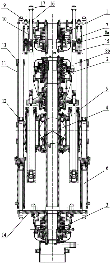
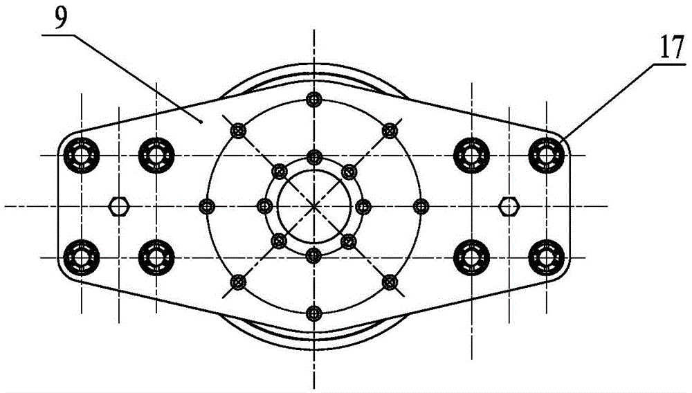
[0016] As shown in the figure: the three-chuck clamping system device in the embodiment is used on the tunnel drilling rig, and it mainly consists of an upper chuck 1, a main chuck 2, a lower chuck 3, a gyrator 4, a lifting cylinder 5, and a pushing cylinder 6. Shackle cylinder 7, connecting guide rod 8, upper chuck mounting plate 9, guide rod 10, guide sleeve 11, guide ring 12, anti-off nut 13, lower chuck mounting plate 14, bracket plate 15, return spring 16 And limit nut 17 forms.

[0017] Such as figure 1 , figure 2 As shown, the main chuck 2 is used to clamp and fix the drill pipe, and the gyrator 4 is used to transmit power to make the drill pipe rotate. On the gyrator 4, several vertical lifting cylinders 5 distributed in a circle are arranged. , the cylinder body of the lift cylinder 5 is fixed on the gyrator 4, and the piston rod end of the lift c...


PUM


Abstract

The invention relates to a three-chuck clamping system device. The three-chuck clamping system device comprises a main chuck, a gyrator and lifting oil cylinders. The three-chuck clamping system device is characterized in that the main chuck is provided with a connecting guide rod, the connecting guide rod penetrates through an upper chuck mounting plate, and the upper chuck mounting plate can only move in a lifting mode on a guide segment of the connecting guide rod. An upper chuck is arranged over the main chuck, and the upper chuck is located underneath the upper chuck mounting plate and fixedly mounted on the upper chuck mounting plate. Shackling oil cylinders are arranged on the periphery of the upper chuck. Shackling oil cylinder bodies are fixedly connected to the connecting guide rod. Piston rod ends of the shackling oil cylinders are upwards connected to the upper chuck mounting plate. The upper ends of guide rods are connected to the periphery of the upper chuck mounting plate, the guide rods are placed in guide sleeves, and the guide sleeves are fixed to the gyrator. The lower ends of the guide sleeves are connected with the tail ends of thrust oil cylinder bodies. Piston rod ends of thrust oil cylinders are downwards connected with a lower chuck mounting plate. A lower chuck is mounted at the bottom of the lower chuck mounting plate. The lower chuck and the main chuck are coaxial. The three-chuck clamping system device can achieve automatic shackling, so labor intensity is lowered, and working efficiency is improved.

Description

technical field [0001] The invention relates to a tunnel drilling rig, in particular to a three-chuck clamping system device on the tunnel drilling rig, and belongs to the technical field of drilling engineering machinery. Background technique [0002] At present, tunnel drilling rigs are equipment for drilling construction in tunnels. There are mainly three types of existing tunnel drilling rigs: the first type is ordinary engineering core surface drilling rigs. This kind of drilling rig has no upper and lower clamping devices. When the drilling rig is drilling upwards, the drill pipe is easy to slide down because there is no hole holder; the second type is a bulk tunnel drilling rig, which has small drilling capacity and poor stability; the third type is Full-hydraulic drilling rigs. At present, some of these drilling rigs are imported. The price of imported full-hydraulic drilling rigs is high, the maintenance cost is high, and the operation level of the captain is very h...

Claims


Application Information

Patent Timeline
Patent Type & Authority Applications(China)
IPC IPC(8): E21B19/10
CPCE21B19/10
Inventor 朱利根王小虎
Owner JIANGSU WUXI MINERAL EXPLORATION MASCH GENERAL FAB CO LTD
Learn More