Eureka AIR delivers breakthrough ideas for toughest innovation challenges, trusted by R&D personnel around the world.

Control structure and method used for reducing separation loss of low-pressure turbine blades

A low-pressure turbine and control structure technology, which is applied in the direction of engine components, machines/engines, mechanical equipment, etc., can solve the problems of reducing applicability, achieve the effect of reducing separation loss and promoting momentum exchange

Active Publication Date: 2015-07-22
INST OF ENGINEERING THERMOPHYSICS - CHINESE ACAD OF SCI
View PDF5 Cites 9 Cited by
  • Summary
  • Abstract
  • Description
  • Claims
  • Application Information

AI Technical Summary

Problems solved by technology

But like all active control schemes, VGJ requires a complex control mechanism and air source supply system, which greatly reduces its applicability

Method used


Image

  • Control structure and method used for reducing separation loss of low-pressure turbine blades
  • Control structure and method used for reducing separation loss of low-pressure turbine blades
  • Control structure and method used for reducing separation loss of low-pressure turbine blades

Examples


Embodiment Construction

[0019] In order to make the object, technical solution and advantages of the present invention clearer, the present invention will be further described in detail below with reference to the accompanying drawings and examples.

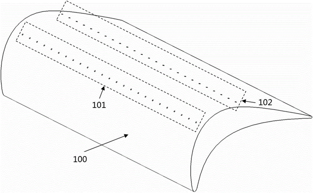
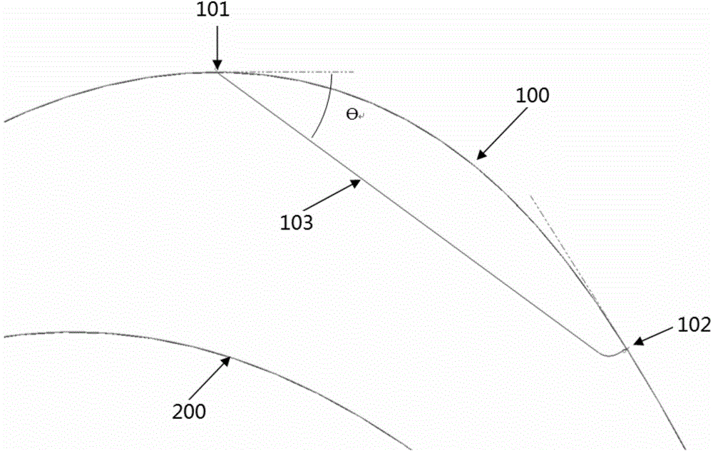
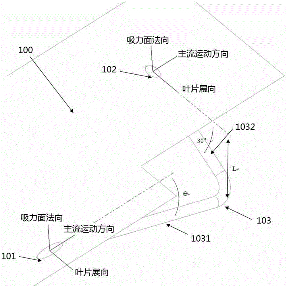
[0020] For the cruising state of the aero-engine, the suction surface of the low-pressure turbine blade is easy to separate, and the ultra-high-load low-pressure turbine blade shape is designed for engine weight reduction. The reverse pressure gradient in the diffuser section of the cascade channel is intensified, resulting in more serious separation loss and a sharp increase in turbine efficiency. To reduce the problem of low-pressure turbine blade separation, the present invention provides a control structure and method for reducing the separation loss of low-pressure turbine blades. , the rows of low-pressure turbine blades at all levels are arranged in the turbine channel, and each of the low-pressure turbine blades includes a suction surface and a p...


PUM


Abstract

The invention discloses a control structure and method used for reducing the separation loss of low-pressure turbine blades. The ultrahigh load low-pressure turbine blades are designed for reducing the weight of an engine and solving the problems that at the cruise state of the aero-engine, the incoming flow air density is low, suction faces of low-pressure turbine blades are prone to separating, the adverse pressure gradient of a diffuser of a blade lattice channel is intensified, the separating loss becomes more serious, and the turbine efficiency is reduced sharply. The control structure and method used for reducing the separation loss of the low-pressure turbine blades are suitable for the high-load and ultrahigh-load low-pressure turbine blades of the aero-engine. Air guiding holes are formed in the appropriate positions of the suction faces of turbine blades, spraying holes are formed in the downstream positions of the air guiding holes, and communicating pipelines are arranged between the air guiding holes and the corresponding spraying holes. According to the structure, air guiding is achieved through the air guiding holes in the upstream wake, the airflow is sprayed to the main flow at the spraying holes at the downstream positions, the airflow energy of an attaching face layer is increased, downstream separating of the spraying holes is eliminated, and therefore the working efficiency of a low-pressure turbine is improved, and the working margin of the low-pressure turbine is enlarged.

Description

technical field [0001] The invention relates to a control structure and method for reducing the separation loss of low-pressure turbine blades, which is suitable for aero-engines and can effectively reduce the separation loss of turbine blades and improve engine efficiency. Background technique [0002] The high bypass ratio turbofan engine has the advantages of low fuel consumption, low pollution and high thrust, and has become the preferred power for civil aircraft today. For an engine with a large bypass ratio, 80% of its thrust comes from the fan part, which is driven by the low-pressure turbine, which results in more stages of the low-pressure turbine and higher weight; at the same time, because the turbine is a hot-end part, the turbine blades are usually The use of denser nickel-based alloys with better high-temperature performance rather than lower-density titanium alloys further increases the weight of the low-pressure turbine. According to statistics, the weight o...

Claims


Application Information

Patent Timeline
IPC IPC(8): F01D17/10
Inventor 孙爽雷志军卢新根杜强
Owner INST OF ENGINEERING THERMOPHYSICS - CHINESE ACAD OF SCI
Why Eureka
Eureka Blog
Learn More