Combined arrangement structure of four outlets of dust remover and rear smoke and air systems of two rows of induced draft fans for power plant

An arrangement structure, wet electrostatic precipitator technology, applied in the directions of induced draft, lighting and heating equipment, combustion methods, etc., can solve the problems of long flue, large area, large flue resistance, etc. Small footprint and uniform smoke flow field

Active Publication Date: 2015-07-22
CHINA ENERGY ENG GRP GUANGDONG ELECTRIC POWER DESIGN INST CO LTD
View PDF8 Cites 4 Cited by
  • Summary
  • Abstract
  • Description
  • Claims
  • Application Information

AI Technical Summary

Problems solved by technology

[0005] The purpose of the present invention is to provide a power plant with four outlets and a double-row induced draft fan for dust collectors in order to solve the technical problems of the existing coal-fired the

Method used


Image

  • Combined arrangement structure of four outlets of dust remover and rear smoke and air systems of two rows of induced draft fans for power plant
  • Combined arrangement structure of four outlets of dust remover and rear smoke and air systems of two rows of induced draft fans for power plant
  • Combined arrangement structure of four outlets of dust remover and rear smoke and air systems of two rows of induced draft fans for power plant

Examples


Embodiment Construction

[0025] The present invention will be further described in detail below in conjunction with the accompanying drawings.

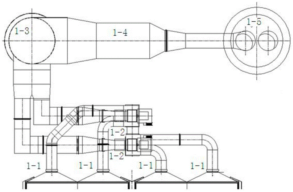
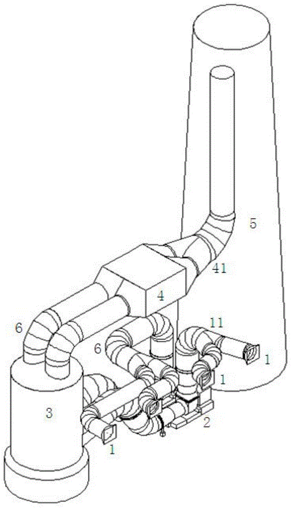
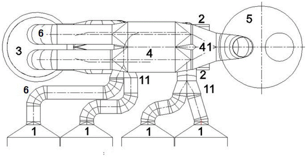
[0026] refer to Figure 2 to Figure 4 , the joint layout structure of the four outlets of the dust collector for the power plant and the rear flue air system of the double row induced draft fan shown in this embodiment, including four outlets of the dust collector 1, the structure of the induced draft fan 2), the desulfurization absorption tower 3, and the wet electrostatic precipitator 4 And the chimney 5, the induced draft fan structure 2 is composed of two induced draft fans to form a double row induced draft fan structure, and every two dust collector outlets 1 are connected to the air inlet of an induced draft fan; the air outlets of the two induced draft fans are respectively connected to the desulfurization absorption tower 3, the air outlet of the desulfurization absorption tower 3 is connected to the air inlet of the chimney 5 through the wet electro...


PUM


Abstract

The invention relates to a combined arrangement structure of four outlets of a dust remover and rear smoke and air systems of two rows of induced draft fans for a power plant. The combined arrangement structure comprises the four outlets of the dust remover, an induced draft fan structure, a desulfurizing absorption tower, a wet electric dust remover and a chimney, wherein the induced draft fan structure is a two-row induced draft fan structure which is composed of two induced draft fans, and every two outlets of the dust remover are connected with an air inlet of one induced draft fan; air outlets of the two induced draft fans are connected with an air inlet of the desulfurizing absorption tower, and an air outlet of the desulfurizing absorption tower is connected with an air inlet of the chimney through the wet electric dust remover; the desulfurizing absorption tower is of a vertical structure, an air inlet of the desulfurizing absorption tower is formed in the lower portion of the side wall, and the air outlet of the desulfurizing absorption tower is formed in the top; the induced draft fan structure and the four outlets of the dust remover are located between the desulfurizing absorption tower and the chimney, the induced draft fan structure is located below the four outlets of the dust remover, the wet electric dust remover is located above the four outlets of the dust remover, a wet electric dust remover structure is located over the induced draft fans, the outlets of the dust remover are horizontally arranged, an air inlet of the induced draft fan structure is vertically arranged, and an air outlet of the induced draft fan structure is horizontally arranged. The combined arrangement structure is low in cost, small in occupied area, and good in operating effect.

Description

technical field [0001] The invention relates to a joint layout structure of the rear flue air system of four outlets of a dust collector and a double-row induced draft fan for a power plant, and belongs to the technical field of power plant smoke exhaust and ventilation equipment. Background technique [0002] In a coal-fired thermal power plant project, the distance from the first column of the boiler to the center line of the chimney is one of the important land occupation indicators. Most of the equipment in the flue gas system is arranged behind the furnace, while the boiler room frame, front flue and dust collector The layout is relatively fixed, and the optimization of the layout after the furnace is mainly concentrated after the dust collector. Regarding the structural form of the flue air system after the dust collector, the main structural forms at home and abroad basically adopt the arrangement structure of each equipment, that is, the induced draft fan 1-2 is arra...

Claims


Application Information

Patent Timeline
IPC IPC(8): F23J15/02F23L17/00
Inventor 范旭杨劲潘灏刘建强张超昱唐晖
Owner CHINA ENERGY ENG GRP GUANGDONG ELECTRIC POWER DESIGN INST CO LTD
Why Eureka
Try Eureka