
Contactless voltage stabilizer

A voltage stabilizing device and non-contact technology, applied in the field of electric power, can solve problems such as insufficient protection functions, restricting the development of traditional voltage stabilizers, and unbalanced output voltage, so as to improve the service life and safety of equipment, strong overload capacity, and compensation wide range of effects

Inactive Publication Date: 2015-07-22
ANHUI GEMINI ELECTRIC TECH
View PDF6 Cites 25 Cited by
  • Summary
  • Abstract
  • Description
  • Claims
  • Application Information

AI Technical Summary

Problems solved by technology

④: Cannot solve the problem of unbalanced output voltage caused by unbalanced three-phase input voltage ⑤: Insufficient protection function, etc., which restrict the development of traditional voltage regulators

Method used


Image

  • Contactless voltage stabilizer
  • Contactless voltage stabilizer
  • Contactless voltage stabilizer

Examples


Embodiment Construction

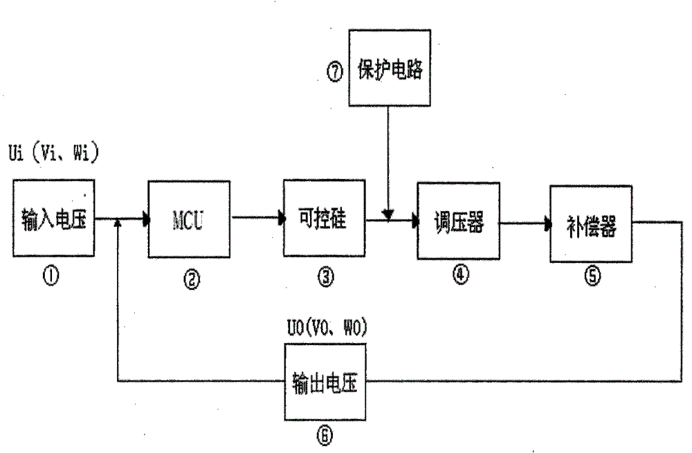
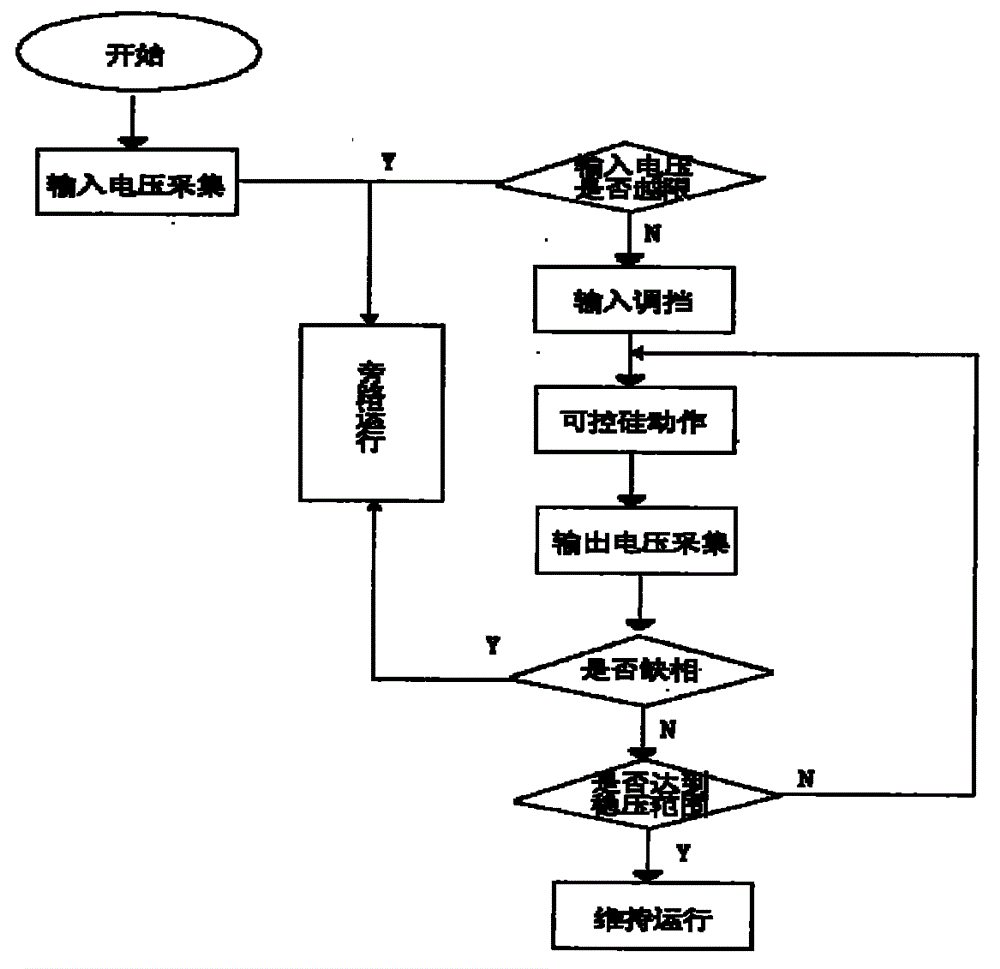
[0020] Principle introduction: the present invention is divided into two parts, the primary circuit and the control circuit.

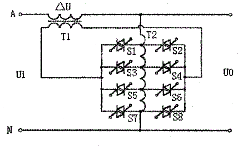
[0021] figure 1 It is the connection method between the thyristor of phase A, the voltage regulating transformer and the compensation transformer, and the connection method of the other two phases is similar. In the figure, T1 represents the compensation transformer, T2 represents the voltage regulating transformer, and S1~S8 are thyristors. The primary winding of the voltage regulating transformer is connected in a Y shape and connected to the output terminal of the voltage stabilizer, the secondary winding is connected to the primary winding of the compensator, and the secondary winding of the compensator is connected to the main circuit. Now take the A phase as an example. How a contactless voltage regulator works. UO=Ui+ΔU, where UO is the output voltage, Ui is the input voltage, and ΔU is the compensation voltage of phase A of the regulator. Whe...


PUM


Abstract

The invention provides a contactless voltage stabilizer to improve voltage quality for users and relates to the electric field, in particular to the field of voltage quality optimizing devices. Existing voltage stabilizers have the disadvantages that a carbon brush is prone to abrasion and needs to be replaced frequently; reaction speed is slow, and using safety of equipment is affected; three-phase integrated adjustment is adopted, and three-phase equilibrium can not be achieved. According to the contactless voltage stabilizer, silicon controlled rectifier gear shift is adopted, and a power electronic device is adopted to replace a mechanical part; carbon brush abrasion and ultrahigh or ultralow voltage at the starting moment are completely avoided structurally; a single-chip microcomputer serves as a main control chip to control a silicon controlled rectifier to be switched on and off, reaction speed is high, efficiency is high, and safety performance is high; a three-phase independent adjustment structure is adopted, and voltage of a certain phase can be adjusted independently, so that output disequilibrium caused by input disequilibrium is avoided.

Description

1. Technical field [0001] The invention relates to the field of electric power, in particular to a power quality optimization device. 2. Background technology [0002] With the development of science and technology, the number of electrical equipment is increasing day by day, but the aging and development of power transmission and distribution facilities, poor design and insufficient power supply cause the voltage of end users to be too low, while the voltage of end users is often too high, and the electrical equipment is particularly It is a high-tech and precision instrument with strict voltage requirements, and it is always in danger. The various loads of the power supply grid will have a certain impact on the grid itself and affect the work of the load. [0003] In response to the above situation, voltage regulators came into being, which can be roughly divided into the following categories: [0004] 1. Ferromagnetic resonant AC voltage stabilizer: an AC voltage stabili...

Claims


Application Information

Patent Timeline
IPC IPC(8): G05F1/56
Inventor 程树林
Owner ANHUI GEMINI ELECTRIC TECH
Learn More