
Electron emission device, manufacturing method thereof and display

一种电子发射装置、电子发射的技术,应用在电极系统制造、放电管/灯的制造、图像/图形显示管等方向,能够解决电子发射率低、平均动能高等问题,达到提高电子出射率、提高出射率的效果

Active Publication Date: 2015-07-22
TSINGHUA UNIV +1
View PDF12 Cites 0 Cited by
  • Summary
  • Abstract
  • Description
  • Claims
  • Application Information

AI Technical Summary

Problems solved by technology

[0005] The MISM type electron emission source needs to have enough average kinetic energy for electrons to pass through the upper electrode and escape into the vacuum. However, in the MISM type electron emission source in the prior art, it is necessary to overcome the problem when electrons enter the upper electrode from the semiconductor layer. Potential barriers tend to be higher than the average kinetic energy of electrons, resulting in low electron emission rates

Method used


Image

  • Electron emission device, manufacturing method thereof and display
  • Electron emission device, manufacturing method thereof and display
  • Electron emission device, manufacturing method thereof and display

Examples


Embodiment Construction

[0029] The electron emission source, electron emission device and display according to the embodiments of the present invention will be described in detail below with reference to the accompanying drawings.

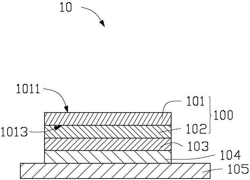
[0030] see figure 1 , The first embodiment of the present invention provides an electron emission source 10 , which includes: a first electrode 100 , an insulating layer 103 , and a second electrode 104 . The insulating layer 103 is stacked between the first electrode 100 and the second electrode 104 . The first electrode 100 is an electron emission end of the electron emission source 10 .

[0031] Further, the electron emission source 10 can be disposed on the surface of a substrate 105 , and the second electrode 104 is disposed on the surface of the substrate 105 . The substrate 105 is used to support the electron emission source 10 . The material of the substrate 105 can be selected from hard materials such as glass, quartz, ceramics, diamond, silicon wafers, or fle...


PUM

PropertyMeasurementUnit
aperture sizeaaaaaaaaaa
widthaaaaaaaaaa
widthaaaaaaaaaa

Abstract

An electron emission device includes a number of second electrodes intersected with a number of first electrodes to define a number of intersections. The first electrode includes a carbon nanotube layer and a semiconductor layer coated on the carbon nanotube layer. An insulating layer is sandwiched between the first electrode and the second electrode at each of the number of intersections, wherein the semiconductor layer is sandwiched between the insulating layer and the carbon nanotube layer.

Description

technical field [0001] The invention relates to an electron emission device, its preparation method and display. Background technique [0002] Electron emission display devices are an indispensable part in various vacuum electronic devices and equipment. In the field of display technology, electron emission display devices can be widely used in automobiles, household audio-visual appliances, industrial instruments and other fields due to their advantages of high brightness, high efficiency, large viewing angle, low power consumption and small size. [0003] Generally, there are two types of electron emission sources used in electron emission display devices: hot cathode electron emission sources and cold cathode electron emission sources. Cold cathode electron emission sources include surface conduction electron emission sources, field electron emission sources, metal-insulator-metal (MIM) type electron emission sources, etc. [0004] On the basis of the MIM type electron ...

Claims


Application Information

Patent Timeline
Patent Type & Authority Applications(China)
IPC IPC(8): H01J1/308H01J9/02H01J31/12
CPCH01J31/12H01J29/02H01J29/18H01J1/308H01J9/02H01J9/022H01J1/312H01J31/127H01J2201/30461H01J2201/30469H01J2201/3125H01J2329/0449H01J2329/0455H01J2329/0484H01J2329/0478
Inventor 柳鹏李德杰张春海周段亮杜秉初范守善
Owner TSINGHUA UNIV
Learn More