Self-walking device and rotary cultivator with same

A self-propelled device and traveling wheel technology, applied in the field of rotary tillers, can solve the problems of low traction force, low technology content, increased chassis frame load, etc., and achieve the effects of reducing belt slippage, optimizing transmission mode, and reducing power loss.

Inactive Publication Date: 2015-07-29
XINGGUANG AGRI MACHINERY
View PDF5 Cites 0 Cited by
  • Summary
  • Abstract
  • Description
  • Claims
  • Application Information

AI Technical Summary

Problems solved by technology

[0002] The layout of the existing products on the market is unreasonable. The diesel engine is arranged horizontally, and is connected with the travel gearbox and the power output transmission box by a pulley transmission. The traction force is small and the left and right centers of gravity are offset. Lost (about 15% smaller than the direct connection between the engine and the power transmission box through mechanical parts); the engine is seriously offset and the left and right centers of gravity are offset; mechanical variable speed walking: loud noise, poor reliability, and low technological content
It is easy to cause energy loss, the transmission connection method is complicated, there are many parts, the space utilization rate is low, and the mass of the whole machine is large, which indirectly increases the load on the chassis frame and deteriorates the reliability.
[0003] Aiming at the disadvantages of unreasonable layout, low transmission efficiency and heavy chassis load in the prior art, the present invention makes further improvements

Method used


Image

  • Self-walking device and rotary cultivator with same
  • Self-walking device and rotary cultivator with same
  • Self-walking device and rotary cultivator with same

Examples


Embodiment Construction

[0024] The technical solutions in the present invention will be clearly and completely described below in conjunction with the accompanying drawings in the present invention.

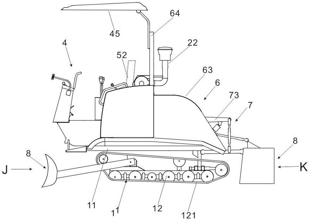
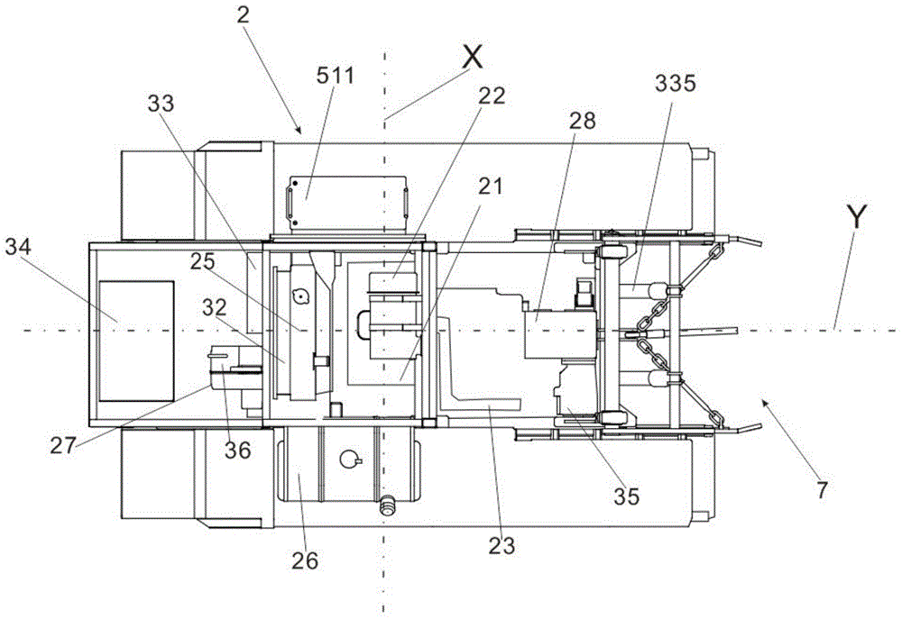
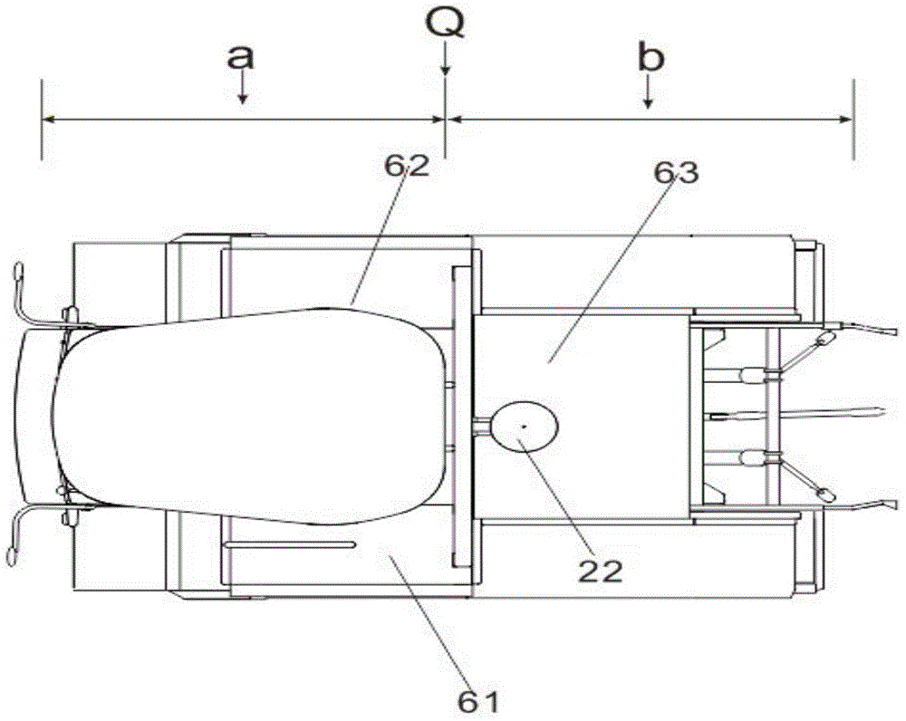
[0025] Such as figure 1 , figure 2 , image 3 , Figure 4 Shown, a kind of self-propelled device comprises walking system 1, power system 2, control system 4, suspension system 7, supporting system 8, and walking system is made up of chassis frame 11 and walking wheel train 12, and walking wheel train 12 is installed on On the support below the chassis frame 11, the power system 2 and the steering system 4 are installed above the chassis frame, and the suspension system 7 is installed at the rear of the chassis frame. Power system 2 comprises engine 21, power output transmission box 28, hydraulic pump 35, hydraulic motor 36, travel gearbox 27, engine 21 links to each other with power output transmission box 28, power output transmission box 28 is connected with hydraulic pump 35 and hydraulic motor ...


PUM


Abstract

The invention relates to a self-walking device and a rotary cultivator with the same. The self-walking device is applicable to crawler-type rotary cultivators and comprises a walking system, a power system, an operation system, a hanging system and a matching system. The self-walking device is characterized in that the walking system comprises a chassis frame and a walking gear train, the walking gear train is mounted on a support below the chassis frame, the power system and the operation system are mounted above the chassis frame, the hanging system is mounted in the rear of the chassis frame, a hydraulic pump on an output transmission case is connected with a hydraulic motor on a walking gearbox to drive the integrated rotary cultivator to run, so that fewer related transmission elements are used, noise is reduced, the load of the chassis frame is indirectly reduced, the weight of the integrated rotary cultivator is reduced, the reliability of a chassis is improved, the rotary cultivator easily runs in rotten fields, and components are bilaterally and symmetrically arranged on the chassis frame in a roughly cross shape and a rear-loaded mode. After accessories are additionally arranged on a tractor, front, rear, left and right centers of gravity are balanced, the rotary cultivator is easily operated in walking and working states, an engine is longitudinally placed, so that arrangement is more balanced and more convenient, and a transmission mode is optimized.

Description

technical field [0001] The invention relates to the technical field of agricultural machinery, in particular to a self-propelled device and a rotary cultivator equipped with the self-propelled device. Background technique [0002] The layout of the existing products on the market is unreasonable. The diesel engine is arranged horizontally, and is connected with the travel gearbox and the power output transmission box by a pulley transmission. The traction force is small and the left and right centers of gravity are offset. Lost (about 15% smaller than the direct connection between the engine and the power transmission box through mechanical parts); the serious offset of the engine causes the left and right center of gravity to be offset; mechanical variable speed walking: loud noise, poor reliability, and low technological content. It is easy to cause energy loss, the transmission connection method is complicated, there are many parts, the space utilization rate is low, and ...

Claims


Application Information

Patent Timeline
Patent Type & Authority Applications(China)
IPC IPC(8): A01B51/02A01B33/00
Inventor 邱扬扬顾伟华
Owner XINGGUANG AGRI MACHINERY
Why Eureka
Try Eureka