

High-precision vertical type machining center
A vertical machining center, high-precision technology, applied in the direction of metal processing, metal processing equipment, metal processing machinery parts, etc., can solve the problem of decreased machining accuracy of the machining center, easy chips falling on the guide rail, poor working stability, etc. problems, to achieve the effect of improving machining accuracy, good protection effect, and strong overall rigidity
- Summary
- Abstract
- Description
- Claims
- Application Information
AI Technical Summary
Problems solved by technology
Method used
Image

Examples
Embodiment Construction
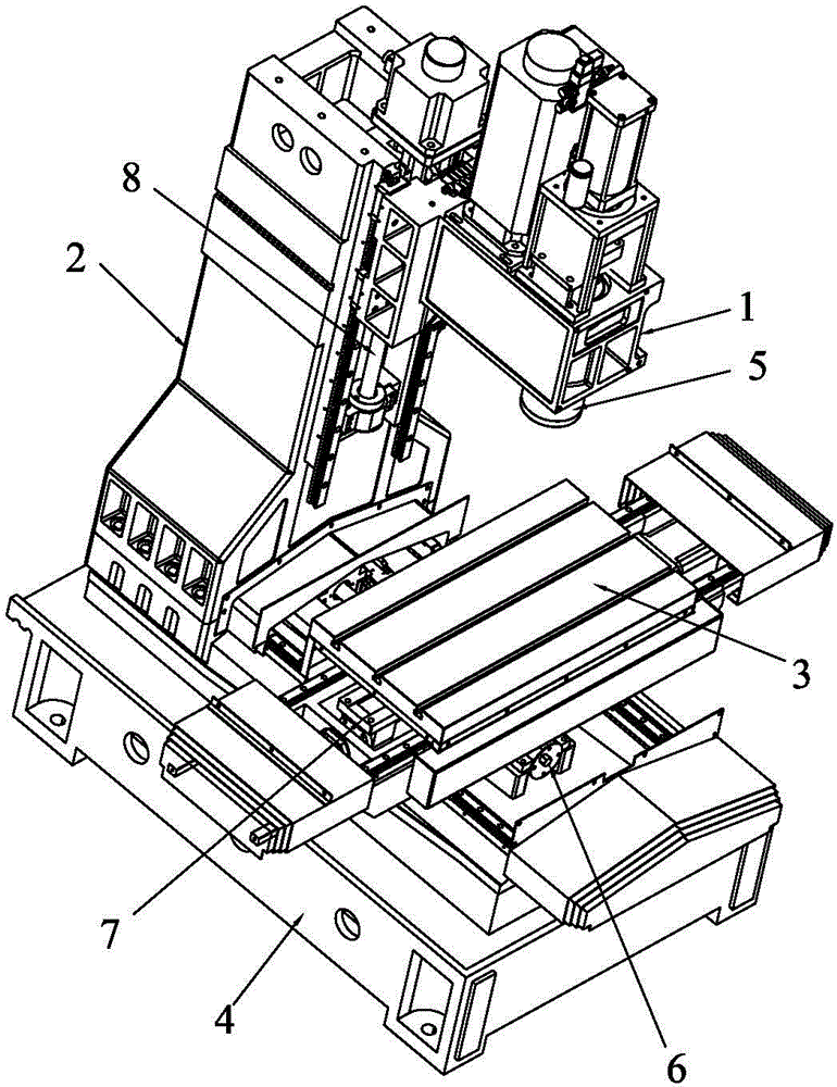
[0025] see Figure 1 to Figure 8 , a kind of high-precision vertical machining center provided by the present embodiment, it comprises base 4, column 2, workbench 3, main shaft box 1, PLC controller and the machining center that is respectively connected with this PLC controller and is controlled by it Main shaft assembly 5 , Y-axis moving mechanism 6 , X-axis moving mechanism 7 and Z-axis moving mechanism 8 , the column 2 is arranged at the rear of the base 4 , and the Y-axis moving mechanism 6 is arranged at the front of the base 4 .
[0026] The spindle housing 1 is arranged on the column 2 through the Z-axis moving mechanism 8. The spindle housing 1 includes a spindle installation horizontal part 11 and a slide seat installation vertical part 12. The slide seat installation vertical part 12 is vertically arranged on the spindle installation horizontal part. 11, the back of the sliding seat installation vertical part 12 is provided with a column slider installation position...
PUM
 Abstract
Description
Claims
Application Information