
Single-plate unmanned operation rotary cutter

A technology of rotary cutting machine and veneer, which is applied in the manufacture of veneer, wood processing equipment, manufacturing tools, etc. It can solve the problems of low production efficiency and high labor intensity of workers, achieve convenient production, simple structure, and change manual production. mode effect

Inactive Publication Date: 2015-07-29
许思光
View PDF8 Cites 0 Cited by
  • Summary
  • Abstract
  • Description
  • Claims
  • Application Information

AI Technical Summary

Problems solved by technology

[0003] The purpose of the present invention is to overcome the deficiencies of the above-mentioned prior art, and provide a veneer unmanned operation rotary cutting machine, which mainly solves the problems of the prior art that the machine needs to be manually operated, the labor intensity of the workers is high, and the production efficiency is low.

Method used


Image

  • Single-plate unmanned operation rotary cutter
  • Single-plate unmanned operation rotary cutter
  • Single-plate unmanned operation rotary cutter

Examples


Embodiment 1

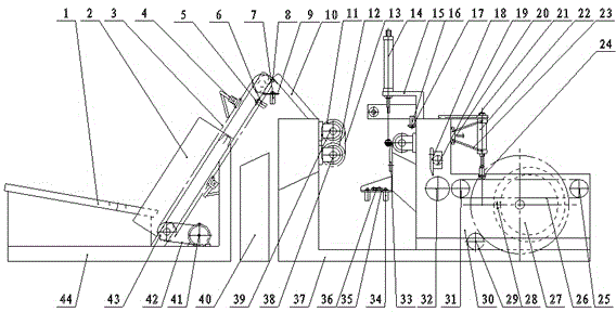
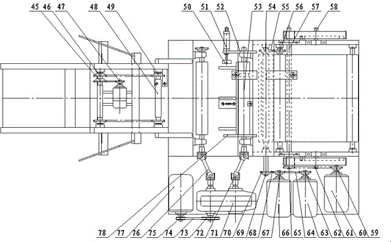
[0016] Example 1, see figure 1 , figure 2 , processed and welded to make a feeding frame 44, a rotary cutting frame 37, and a movable knife table 30, all gears, sprockets, chains, pneumatic components, electrical components, etc. are purchased in the market; the programmable control box 40 preset programs, all rollers , sprocket shaft, and both ends of the gear shaft are equipped with seated bearings;

[0017] Loading machine part: install the storage rack 1, the guide plate 2, the first motor 41, the first sprocket shaft 43, the second sprocket shaft 48, the first photoelectric bracket 5, and the second photoelectric bracket on the loading frame 44 9; install the fifth sprocket 47 on the first motor 41; install the third sprocket 45 and the fourth sprocket 46 on the first sprocket shaft 43; install between the fifth sprocket 47 and the third sprocket 45 The third chain 42; the sixth sprocket 49 is installed on the second sprocket shaft 48; the first chain 3 is installed be...

Embodiment 2

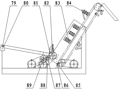
[0020] Example 2, see image 3 , 4 , with embodiment 1, the difference is that the storage rack 1, the guide plate 2, the first motor 41, the first sprocket shaft 43, the second sprocket shaft 48, the first photoelectric support are installed on the feeding frame 44 5. The second photoelectric support 9, the storage rack support 80, the fifth photoelectric support 86, the sixth photoelectric support 88, the sixth motor 90, the seventh motor 92, the third sprocket shaft 91, and the fourth sprocket shaft 97; The fifth sprocket 47 is installed on a motor 41; the third sprocket 45 and the fourth sprocket 46 are installed on the first sprocket shaft 43; the third chain 42 is installed between the fifth sprocket 47 and the third sprocket 45 Install the sixth sprocket 49 on the second sprocket shaft 48; install the first chain 3 link between the fourth sprocket 46 and the sixth sprocket 49; install the first driving lever 4 on the first chain 3, The second roller 84 is installed on...


PUM


Abstract

The invention discloses a single-plate unmanned operation rotary cutter. The single-plate unmanned operation rotary cutter is characterized by comprising a feeding machine part, a rotary cutting chopping machine part and a programmable control box, wherein a photoelectric sensor for detecting raw materials, a material storage rack swing device, a mechanical feeding device, a feeding device and a raw material automatic guiding device are mounted on the feeding machine, and raw materials can be accurately and automatically fed onto the rotary cutting chopping machine; another photoelectric sensor for detecting the positions of the raw materials is mounted on the rotary cutting chopping machine, so that different parameters of the raw materials can be accurately and quickly judged, accurate feeding of a movable tool post is instructed, and the auxiliary time is reduced; moreover, Seppi breakage for suspension is given out; the labor intensity of workers is alleviated, the failure rate of tail belt is reduced, unmanned machine operation is realized, a traditional manual production mode is changed, the production efficiency is improved, and the rotary cuter is simple in structure and convenient to manufacture.

Description

Technical field: [0001] The invention relates to the technical field of wood processing machinery, in particular to a veneer unmanned rotary cutter, which is used for log processing veneer machinery. Background technique: [0002] At present, the existing log veneer processing process is first to use a rounder or a rotary cutter to process the log into a cylindrical shape, and then send it to the rotary cutter through mechanical or manual handling or a feeder, and then manual operation. Cylindrical semi-finished products are rotary cut into strip-shaped veneers, and then go through the skinning mechanism to form veneers according to the required width, and then the finished veneers are sorted and stored by manual or automatic sorting machines. The biggest disadvantage of the processing process is that the rotary cutting machine must be operated manually, the labor intensity of the workers is very high, the machine cannot run at high speed, and the production efficiency is lo...

Claims


Application Information

Patent Timeline
IPC IPC(8): B27L5/02
CPCB27L5/02
Inventor 许思光赵富田王敏
Owner 许思光
Learn More