Liquefied gas combustion chamber with outlet equipped with swirling vanes

A swirl vane and combustion chamber technology, applied in the field of liquefied gas combustion chamber, can solve problems such as poor heat exchange uniformity and high heat load, and achieve the effects of simple structure, reduced thermal shock, and wide fuel expansibility

Active Publication Date: 2015-07-29
BEIHANG UNIV
View PDF10 Cites 7 Cited by
  • Summary
  • Abstract
  • Description
  • Claims
  • Application Information

AI Technical Summary

Problems solved by technology

In this case, the high-temperature gas after combustion is discharged from the single-tube combustion chamber in a manner close to jet flow, and directly performs strong impact heat exchange with the heat exchange

Method used


Image

  • Liquefied gas combustion chamber with outlet equipped with swirling vanes
  • Liquefied gas combustion chamber with outlet equipped with swirling vanes
  • Liquefied gas combustion chamber with outlet equipped with swirling vanes

Examples


Embodiment Construction

[0029] The present invention will be described in detail below in conjunction with the accompanying drawings and specific embodiments.

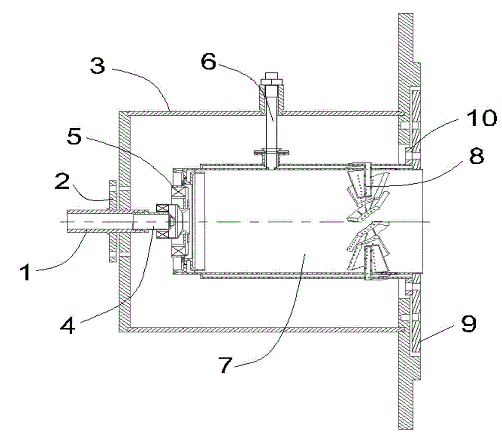
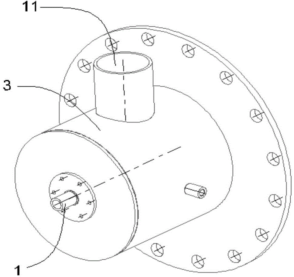
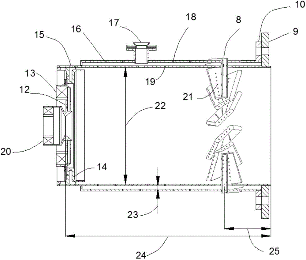
[0030] Such as Figure 1-7 As shown in this embodiment, a liquefied gas combustion chamber with swirling blades at the outlet adopts a single-tube cylindrical combustion chamber structure, and the whole is made of stainless steel. And swirl blade 8 constitutes. The liquefied gas fuel enters the head of the combustion chamber through the oblique small hole of the nozzle 4. Air enters the combustion chamber from the air inlet 11 of the combustion chamber, and part of the air enters the combustion chamber from the inner swirler 20 and the outer swirler 13 to directly participate in combustion, and the swirl generated by the inner swirler 20 completes the mixing with the liquefied gas. The swirl created by the outer swirler 13 forms a recirculation zone to stabilize the flame. Part of the air enters the flame cylinder from the impact wall 16, ...


PUM

PropertyMeasurementUnit
Diameteraaaaaaaaaa

Abstract

The invention discloses a liquefied gas combustion chamber with an outlet equipped with swirling vanes. The liquefied gas combustion chamber adopts a single-tube cylindrical combustion chamber structure and mainly comprises a liquefied gas spray nozzle, a combustion chamber case, a flame tube and the swirling vanes, wherein the swirling vanes are welded to strip-shaped grooves of the flame tube, form certain angles with the axial direction and are uniformly distributed circumferentially; the flame tube and the case are connected by a bolt; liquefied gas enters the head of the combustion chamber from an oblique hole of the spray nozzle, and the combustion of the liquefied gas is completed by using an electrospark lighter; a combustion organization generates strong-swirl stable flame by adopting internal-external two-stage swirlers, and a cooling manner is an impact wall-divergence wall coupled vane gas film hole manner; the swirling direction of an external swirler is the same as that of the swirling vanes of the outlet of the combustion chamber, due to the coupling of swirling, the strength of swirling in the flame tube is strengthened, and the length of flame is shortened; high-temperature combustion gas generated from combustion generates relatively-strong swirling flow when the high-temperature combustion gas passes through the swirling vanes, the high-temperature combustion gas is exhausted from the outlet of the combustion chamber and forms expanding gas flow, and thus, the radial distribution of outlet combustion gas in space is enlarged.

Description

technical field [0001] The invention relates to a combustor using liquefied gas fuel, in particular to a liquefied gas combustor with swirl blades at the outlet Background technique [0002] The concept of the single-tube combustor is derived from the gas turbine combustor. With its simple structure, stable combustion, high combustion efficiency, wide ignition range, easy operation, safety and reliability, it has been widely used in thermal engineering, metallurgy, scientific research and experiment fields. . In particular, the single-tube combustion chamber can be used as a heat source to heat heat exchange equipment such as honeycomb regenerators and heat exchange tubes. [0003] At present, the single-tube combustor generally adopts the structural form of the combustor head and the flame tube. The head of the combustion chamber makes the air entering the combustion chamber generate circumferential momentum through swirlers, radial holes, etc., and completes the mixing o...

Claims


Application Information

Patent Timeline
IPC IPC(8): F23R3/58F23R3/38
Inventor 林宇震韩啸张弛王建臣
Owner BEIHANG UNIV
Why Eureka
Try Eureka