Power conversion device and electric power steering device using the same

A technology of power conversion and equipment, applied in the field of electric steering equipment, can solve problems such as inability to distinguish shunt voltages

Active Publication Date: 2015-07-29
DENSO CORP
View PDF5 Cites 6 Cited by
  • Summary
  • Abstract
  • Description
  • Claims
  • Application Information

AI Technical Summary

Problems solved by technology

For the above reasons, for example, in JP-A-2013-17363 corresponding to US2013 / 0009587, even if an abnormality in which the shunt voltage is fixed to zero due to a short circuit of the shunt resistor occurs, it cannot be distinguished whether the shunt voltage is fixed to zero

Method used


Image

  • Power conversion device and electric power steering device using the same
  • Power conversion device and electric power steering device using the same
  • Power conversion device and electric power steering device using the same

Examples


no. 1 approach

[0034] exist Figure 1 to Figure 8 A power conversion device and an electric power steering device according to a first embodiment of the present disclosure are shown in . Hereinafter, in various embodiments, substantially the same configurations are denoted by the same reference numerals, and repeated descriptions will be omitted.

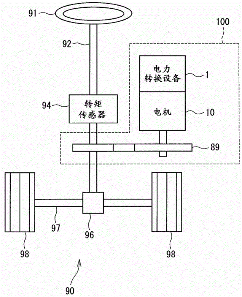
[0035] Such as figure 1 As shown, the power conversion device 1 is applied to an electric power steering device 100 for assisting a driver's steering operation together with a motor 10 as a rotating electric machine.

[0036] figure 1 An overall configuration of a steering system 90 having an electric power steering apparatus 100 is shown. The steering system 90 includes a handle (steering wheel) 91 , a steering shaft 92 , a pinion 96 , a rack shaft 97 , wheels 98 and an electric steering apparatus 100 .

[0037] A handle 91 is connected to a steering shaft 92 . The steering shaft 92 is equipped with a torque sensor 94 for detecting a steerin...

no. 2 approach

[0148] The following will refer to Figure 9 and Figure 10 A second embodiment of the present disclosure will be described.

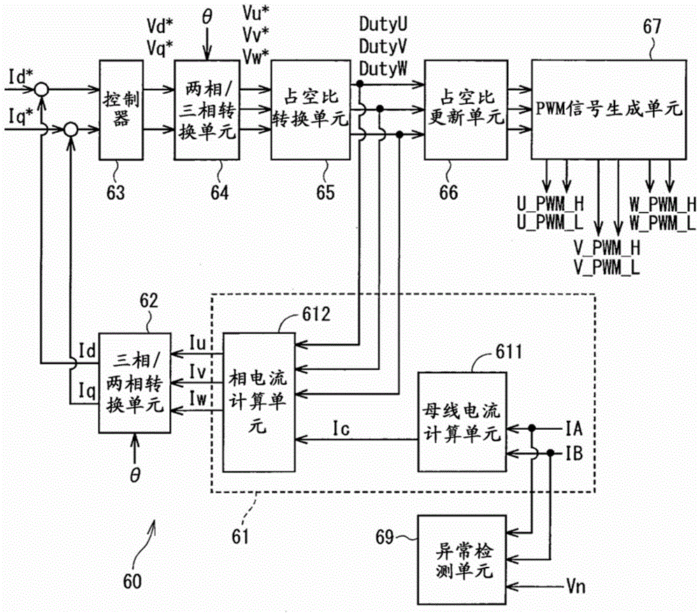
[0149] In the first embodiment, current detection and abnormality detection are performed in the PWM1 cycle. In this embodiment, the corresponding phase currents Iu, Iv, and Iw are calculated based on the current detection values ​​IA and IB in the first cycle of PWM, and based on the pseudo-neutral point voltage Vn and the current detection values ​​IA and IB in the second cycle to perform anomaly detection.

[0150] will refer to Figure 9 The timing of acquiring the current detection values ​​IA and IB will be described.

[0151] The current detection timing according to this embodiment is the same as that in the above embodiment, and the current detection value IA is acquired at times t11, t12, t13, and t14 of the PWM1 cycle and at times t21, t22, t23, and t24 of the PWM2 cycle. and IB.

[0152] In the following, it is assumed that the curren...

no. 3 approach

[0177] exist Figure 11 A third embodiment of the present disclosure is shown in . exist Figure 11 In , configurations other than the microcomputer 60 and the drive circuit unit 71 are omitted. This also applies to Figure 12 to Figure 14 .

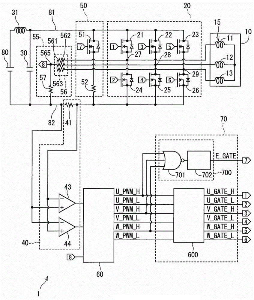
[0178] The driving circuit unit 71 includes an inverter driving circuit 600 and an abnormality checking driving circuit 710 .

[0179] The abnormality check drive circuit 710 includes a logic circuit 711 and an amplifier circuit 712 . Logic circuit 711 is a NOR circuit that is high when all gate signals U_GATE_H, V_GATE_H and W_GATE_H related to driving upper SW 21 to 23 are low.

[0180] The amplifier circuit 712 is the same as the amplifier circuit 702 in the above embodiment.

[0181] In this embodiment, it is possible to directly monitor the abnormality of the gate signals U_GATE_H, V_GATE_H, and W_GATE_H output to the SWs 21 to 23 .

[0182] Also, the same advantages as those in the above embodiment are obtained even in this ...


PUM


Abstract

A power conversion device includes: an inverter that includes high potential side switching elements connected to a high potential side and low potential side switching elements connected to a low potential side, and converts a current for supplying a rotating electric machine; a current detector having a sensor disposed on at least one of a positive bus for connecting the high potential side switching elements and a positive side of a DC power supply or a negative bus for connecting the low potential side switching elements and a negative side of the DC power supply; an energization device that energizes the sensor without passing through the inverter; and a controller that acquires a current detection value from the current detector, and controls the inverter and the energization device. The energization device energizes the sensor when all of high or low potential side switching elements are off.

Description

technical field [0001] The present disclosure relates to a power conversion device and an electric power steering device using the power conversion device. Background technique [0002] Hitherto, a technique is known in which each phase current is detected based on a shunt voltage, which is a voltage between both ends of a shunt resistor arranged on a bus bar of an inverter. For example, in JP-A-2013-17363, the current detection value of the drift current detected in the state where the motor current is assumed to be zero is set as the current offset value, and the current value of the motor current is adjusted according to the offset value. The detection value is compensated. [0003] Even in a normal state, the shunt voltage of the shunt resistors arranged on the bus bars of the inverter may be zero. For the above reasons, for example, in JP-A-2013-17363 corresponding to US2013 / 0009587, even if an abnormality in which the shunt voltage is fixed to zero due to a short cir...

Claims


Application Information

Patent Timeline
Patent Type & Authority Applications(China)
IPC IPC(8): H02M7/5387B62D5/04
CPCH02P27/08B62D5/046B62D5/049H02P29/0241B60W10/08B60W20/00Y02T10/70Y02T10/7072
Inventor 铃木崇志
Owner DENSO CORP
Why Eureka
Try Eureka