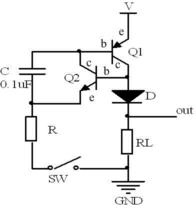
Simple driving circuit with load short circuit protection and self recovery functions
A technology of load short circuit and drive circuit, which is applied in the direction of electrical components, electronic switches, pulse technology, etc., can solve the problems of high cost, complex structure, and many devices, and achieve the effect of convenient and simple production, simple control, and cost reduction
- Summary
- Abstract
- Description
- Claims
- Application Information
AI Technical Summary
Problems solved by technology
Method used
Image
Examples
Embodiment 1
[0021] like figure 1 As shown, the simple drive circuit with load short-circuit protection and self-recovery function includes the first triode Q1, the second triode Q2, the control switch SW, the capacitor C, the diode D, and the current limiting resistor R, where:
[0022] The first transistor Q1 is a PNP transistor, and the second transistor Q2 is an NPN transistor;
[0023] The emitter of the first triode Q1 is connected to the power supply V, the base is connected to the collector of the second triode Q2, and the collector is connected to the load RL through the diode D; the anode of the diode D is connected to the collector of the first triode Q1 , the negative pole is connected to the load RL, and the negative pole of the diode D is the output terminal out of the simple drive circuit, which provides the output current for the load RL;
[0024] The second triode Q2 is used as the core protection tube, its base is connected to the collector of the first triode Q1, and th...
Embodiment 2
[0040]The difference between this embodiment and Embodiment 1 is that in this embodiment, a resistor is used to replace the diode D of the unidirectional conduction device. One end of the resistor is connected to the collector of the first triode Q1, and the other end is connected to the load RL.
[0041] When the load RL is short-circuited, the output terminal out is directly pulled down to the power ground (GND), and the base voltage of the second transistor Q2 is equal to the voltage of the resistor. Maintaining the slight conduction of the second transistor Q2, the second transistor Q2 quickly returns to the slight conduction state from the normal conduction state, and the base current of the first transistor Q1 decreases rapidly accordingly, so that Q1 conducts The passing current Ice, that is, the current at the output terminal out also decreases rapidly. The whole circuit is in the micro-conduction state of extremely low current output (the output current is about a few...
Embodiment 3
[0044] The difference between this embodiment and Embodiment 1 is that in this embodiment, the diode D is canceled or a 0 ohm resistor is used instead of the diode D. In this solution, the second transistor Q2 is the core protection tube for load short-circuit protection. When the load RL is short-circuited, the output terminal out of the simple drive circuit is directly pulled down to the ground, so the second transistor Q2 is turned on from normal The state quickly returns to the micro-conduction state, and the base current of the first triode Q1 decreases rapidly accordingly, so that the driving current of the output terminal of the first triode Q1 also decreases rapidly, and the entire circuit is at an extremely low current output The micro-conduction state realizes the short-circuit protection function. When the short circuit of the load RL is eliminated, the micro-conduction current of the first transistor Q1 passes through the load RL to generate a micro voltage superim...
PUM
| Property | Measurement | Unit |
|---|---|---|
| Capacitance | aaaaa | aaaaa |
| Capacitance | aaaaa | aaaaa |
| Resistance | aaaaa | aaaaa |
Abstract
Description
Claims
Application Information
 - R&D
- Intellectual Property
- Life Sciences
- Materials
- Tech Scout
- Unparalleled Data Quality
- Higher Quality Content
- 60% Fewer Hallucinations
Browse by: Latest US Patents, China's latest patents, Technical Efficacy Thesaurus, Application Domain, Technology Topic, Popular Technical Reports.
© 2025 PatSnap. All rights reserved.Legal|Privacy policy|Modern Slavery Act Transparency Statement|Sitemap|About US| Contact US: help@patsnap.com

