Suction Roll System

A technology of control system and low-voltage system, which is applied in the direction of textiles and papermaking, paper machine, object supply, etc., can solve the problem of no flexibility and achieve the effect of high flexibility

Active Publication Date: 2018-05-01
WINKLER DUNNEBIER GMBH
View PDF8 Cites 0 Cited by
  • Summary
  • Abstract
  • Description
  • Claims
  • Application Information

AI Technical Summary

Problems solved by technology

But the system has no flexibility in controlling suction holes in groups

Method used


Image

  • Suction Roll System
  • Suction Roll System
  • Suction Roll System

Examples


Embodiment Construction

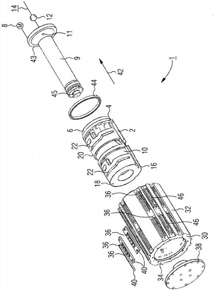
[0030] according to figure 1 The suction roll system is arranged to be used in a device not shown in detail for processing paper or cellulose webs. In this device, the paper web or cellulose web is first guided as a whole by functional rollers (for example deflection rollers, but also cutting or separating rollers). Depending on the intended use of the device, the material web is here cut into a plurality of individual planar pieces (for example paper pieces) or cellulose pieces (for example handkerchiefs or similar objects), which are subsequently conveyed or supplied individually to another a processing position. While the individual blocks are being conveyed further, they can also be deflected, supported or processed, such as punching out windows in the form of other cutting processes, making impressions or the like.

[0031] The suction roll system 1 can be used at any position in the device as individual function rollers or function rolls, and the suction roll system is...


PUM


Abstract

A suction roll system (1) with a rotatably mounted cylindrical suction roll (32), the cylinder jacket (34) of which is provided with a plurality of suction holes (36), which can be selectively connected via a control system individually or in groups to a vacuum system (14), is intended to make possible, in a reliable fashion, particularly short switchover times and also high flexibility, even when groups of a plurality of suction holes (36) are actuated. To this end, according to the invention, the control system comprises a fixedly mounted hollow cylinder (2) projecting into the suction roll (32) and connected by its interior volume (10) to the vacuum system (14), the cylinder jacket (20) of which is penetrated by a number of control slots (22).

Description

technical field [0001] The invention relates to a suction roll system with a rotatably supported cylindrical suction roll, the cylindrical housing of which is provided with a plurality of suction holes, in particular in the form of perforated seams, which can be individually controlled by a control system. They are selectively connected to the low-voltage system either ground or in groups. Furthermore, the invention relates to a device for processing a material web, in particular a paper web or a cellulose web. Background technique [0002] In the paper converting or cellulose converting industries, material webs are often processed. In this case, for example during the manufacture of envelopes, printed products or the like, the paper web is supplied to a further processing station, wherein the paper web is cut, folded, printed or otherwise processed into individual pieces. Likewise, for example, in the manufacture of handkerchiefs, the cellulose-fiber web is subjected to ...

Claims


Application Information

Patent Timeline
Patent Type & Authority Patents(China)
IPC IPC(8): B26D7/18D21F3/10
CPCB65H5/226B65H20/12B65H27/00B65H29/243B65H2406/3312B65H2406/332B65H2406/365B65H2601/324D21F3/10
Inventor 安德斯·林克罗尔夫·马杰维斯基康拉德·波普索斯腾·特夫斯蕾娜·塞格尔尤尔根·韦格
Owner WINKLER DUNNEBIER GMBH
Why Eureka
Try Eureka