Integral optical glass forming mould

An optical glass and molding mold technology, applied in glass molding, glass pressing, glass manufacturing equipment and other directions, can solve the problems affecting the production yield, low molding yield, low molding viscosity, etc., to solve the problem of sticking and molding The problem of stripes, improving the production yield, and solving the effect of forming stripes

Inactive Publication Date: 2015-08-05
HUBEI NEW HUAGUANG NEW INFORMATION MATERIALS CO LTD
View PDF4 Cites 7 Cited by
  • Summary
  • Abstract
  • Description
  • Claims
  • Application Information

AI Technical Summary

Problems solved by technology

However, when this molding method produces lanthanide optical glass with high molding temperature and low molding viscosity, the temperature consistency and uniformity of each part of the mold cannot be improved, and the molten glass is prone to convection streaks during the molding process, which affects production. Yield rate
[0006] The above two patents respectively improved the R angle and surface stripes of the optical glass strip during the molding process by heating or cooling the surface, but neither of them solved the mold sticking problem of the glass during the molding process, especially for high molding temperatures. , forming low-viscosity lanthanide optical glass, the problem of low molding yield has not been resolved

Method used


Image

  • Integral optical glass forming mould
  • Integral optical glass forming mould
  • Integral optical glass forming mould

Examples


Embodiment Construction

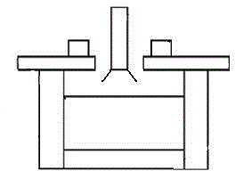
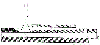
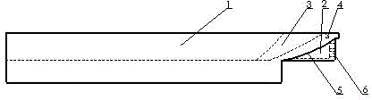
[0021] Such as image 3 , Figure 4 , Figure 5 shown. The integral optical glass forming mold of the present invention includes a forming part 1 and a cooling part 2 . Wherein, the forming part 1 is an integral forming groove, the width of the forming groove is 100-200 mm, and the depth is 40-60 mm. One end of the molding part 1 is open, and the working surface at the other end is a concave working arc surface 3, and the working arc surface 3 is an arc surface of 200°-300°. The bottom surface of the forming groove below the working arc surface 3 is a downwardly convex cooling arc surface 5, and the cooling arc surface 5 is an arc surface of 200°-300°. The thickness between the working arc surface 3 and the cooling arc surface 5 is 10-30mm. The cooling part 2 is a cooling cavity closely attached to the cooling arc surface 5 , and the cooling cavity is provided with cooling holes 6 . The length of the cooling cavity is 50-100mm, and the width is 50-100mm. A thermocouple ...


PUM

PropertyMeasurementUnit
thicknessaaaaaaaaaa
widthaaaaaaaaaa
depthaaaaaaaaaa

Abstract

The invention discloses an integral optical glass forming mould, belongs to the field of an optical glass melting and forming technology, and mainly solves the problems that the glass metal sticky mold and moulded stripes can be easily caused when an optical glass strip is formed. The integral optical glass forming mould is characterized by mainly comprising a forming part and a cooling part, wherein the forming part is an integral forming groove, one end of the forming groove is opened, and an end working surface at another end of the forming groove is a concave working cambered surface; the bottom surface of the forming groove below the end working surface is a lower convex cooling cambered surface, the cooling part is a cooling cavity closely adhered to the cooling cambered surface, and a cooling hole is formed in the cooling cavity; a temperature control thermocouple is arranged above the forming part. The integral optical glass forming mould provided by the invention has the characteristics of the optical glass strip of stable production, high forming temperature and low forming viscosity, thereby being mainly used for the forming of lanthanide series optical glass.

Description

technical field [0001] The invention belongs to the technical field of optical glass fusion molding, in particular to a molding die for optical glass strips, especially for the production of optical glass strips with high molding temperature and low molding viscosity, which has obvious advantages. Background technique [0002] In the field of optical glass melting and forming, the strip forming process is a main forming process. In the molten state, the optical glass is molded and cut into optical glass strips of a certain size. The glass strip forming device is generally composed of a bottom mold, a side mold and a plug. Due to the high temperature of the molten glass, when forming in the mould, a large amount of heat brought by the molten glass makes the temperature of the mold continue to rise, so the mold needs to be continuously cooled through the plug during the production process. Since the cutting edge of the plug is very thin and the heat dissipation is small, loca...

Claims


Application Information

Patent Timeline
Patent Type & Authority Applications(China)
IPC IPC(8): C03B11/06C03B19/02
Inventor 张泰山周希光冦小勇陈超
Owner HUBEI NEW HUAGUANG NEW INFORMATION MATERIALS CO LTD
Why Eureka
Try Eureka