Continuous zooming infrared lens

A technology of infrared lens and zoom lens, which is applied in the field of infrared optics, can solve the problems that the best image plane deviates from the Gaussian image plane, the lens transmittance decreases, and affects the detection and recognition rate, etc., so as to improve the detection distance and imaging quality, and achieve good imaging Effect, the effect of improving system stability

Inactive Publication Date: 2015-08-05
昆明全波红外科技有限公司
View PDF0 Cites 18 Cited by
  • Summary
  • Abstract
  • Description
  • Claims
  • Application Information

AI Technical Summary

Problems solved by technology

The structure of the existing focal lens is very complicated, requiring a lot of lenses, and the infrared zoom lens has no advantage in terms of cost due to the use of scarce germanium materials, and the use of too many lenses will reduce the lens transmittance and affect the detection Recognition rate
On the other hand, the design technology of the continuous zoom infrared lens in the prior art still uses the traditional method, using the Gaussian optical solution method to design the zoom cam curve. This method is effective in dealing with visible light products with a large F number. However, long-wave infrared products live in F1.0 or smaller F-numbers. The reason for aberration will cause the best image plane to deviate from the Gaussian image plane, resulting in image plane displacement and seriously reducing the imaging quality.

Method used


Image

  • Continuous zooming infrared lens
  • Continuous zooming infrared lens
  • Continuous zooming infrared lens

Examples


Embodiment Construction

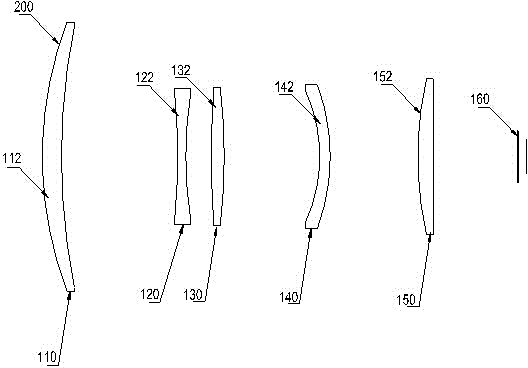
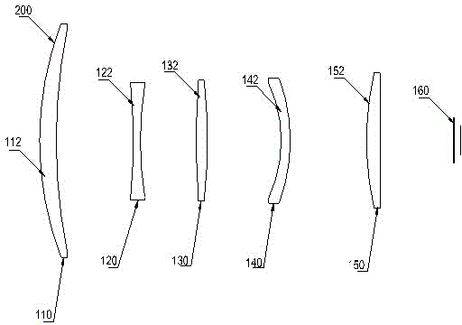
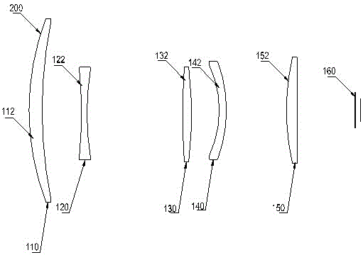
[0018] figure 1 , figure 2 , image 3 They are schematic diagrams of the zoom lens of the embodiment of the present invention at the telephoto, medium-focus and short-focus positions respectively. Figure 1-3 Among them, 200 indicates the side end of the object, and 160 indicates the side end of the image. Such as figure 1 As shown, the zoom lens of this embodiment includes: a first lens group 110 with positive diopter, a second lens group 120 with negative diopter, a third lens group 130 with positive diopter, which are arranged in sequence from the object side to the imaging side. A fourth lens group 140 with negative diopter and a fifth lens group 150 with positive diopter.

[0019] Wherein, the first lens group 110 is a front fixed group for converging and receiving light. The first lens group 110 is composed of a first meniscus germanium positive lens 112 with a positive diopter and a convex surface facing the object side. Since the lenses of the first lens group 1...


PUM


Abstract

The invention relates to a continuous zooming infrared lens, and the lens can improve the imaging quality. The lens comprises a first lens group serving as a front fixed group; a second lens group serving as a zooming group; a third lens group serving as a compensation group; a fourth lens group serving as a rear fixed group; a fifth lens group serving as a focusing group which is used for compensating the offset of an image plane under the condition of different object distances and different temperatures; and a zooming drive cam. The beneficial effects of the lens are that the lens remarkably prolongs the detection operation distance and improves the imaging quality, reduces the cost, and can achieve a good imaging effect. The zooming drive cam which employs the technology of curve fitting to design the curve of the zooming drive cam effectively solve a problem of the offset of the image plane in a zooming process.

Description

technical field [0001] The invention relates to infrared optical technology, in particular to a continuous zoom infrared lens. Background technique [0002] Infrared thermal imaging is a technology that is fully covered, works without light, can detect and identify targets at a long distance, and can detect target temperature. It is widely used in night vision, medical, military, security and other fields, and has broad application prospects and use value. In recent years, the application breadth and depth of infrared imaging technology have made great progress. [0003] When infrared products are used for target detection, the continuous zoom lens can be used to freely change the long and short focal lengths to achieve "wide range search and key monitoring". The structure of the existing focal lens is very complicated, requiring a lot of lenses, and the infrared zoom lens has no advantage in terms of cost due to the use of scarce germanium materials, and the use of too ma...

Claims


Application Information

Patent Timeline
Patent Type & Authority Applications(China)
IPC IPC(8): G02B15/173
CPCG02B15/173
Inventor 金有平张莹昭
Owner 昆明全波红外科技有限公司
Why Eureka
Try Eureka