a solar cell

A solar cell and solar chip technology, applied in the field of solar cells, can solve problems such as reduced energy conversion efficiency, electromagnetic interference, and high voltage stress of switching devices, so as to reduce conduction loss and switching loss, reduce voltage stress, and improve work efficiency Effect

Active Publication Date: 2017-06-16
BEIJING HUANERKANG TECH DEV
View PDF4 Cites 0 Cited by
  • Summary
  • Abstract
  • Description
  • Claims
  • Application Information

AI Technical Summary

Problems solved by technology

At this time, the conversion process of electric energy is actually changed from the original DC-DC to DC-AC-AC-DC, and the energy conversion efficiency of the whole system is reduced.
[0008] The second is to use coupled inductors, but the structure of coupled inductors is complex, which is not conducive to industrial processing, it is difficult to ensure the consistency of the circuit, and it will cause excessive voltage stress of switching devices, which will cause electromagnetic interference and other effects, resulting in large operating losses of the converter.
[0009] The third is to add cascaded boost units, the more units, the greater the voltage gain, but the more circuit components, the more complex the structure
However, this boost circuit requires too many components such as switches, capacitors, and diodes, resulting in a complex circuit structure and high cost.

Method used


Image

  • a solar cell
  • a solar cell
  • a solar cell

Examples


Embodiment Construction

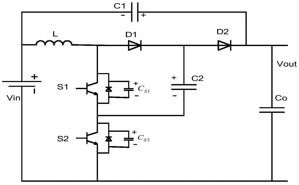
[0039] Depend on image 3 It can be seen that the low-voltage switching stress booster circuit of the present invention includes the input voltage Vin of the optical collection conversion module, switching elements S1, S2, diodes D1, D2, inductor L, input capacitor C1, intermediate capacitor C2 and output capacitor Co. Due to the characteristics of switching devices, switching elements S1 and S2 respectively have parasitic capacitance C S1 、C S2 .

[0040] combined with image 3 The structure of the present invention is described in detail. The specific connection relationship is as follows: the positive pole of the input voltage Vin is connected to one end of the inductance L and the negative end of the input capacitor C1, and the other end of the inductance L is connected to the collector of the switching element S1 and the anode of the diode D1. The emitter of the switching element S1 is connected to the collector of the switching element S2, the emitter of the switching...


PUM


Abstract

The invention discloses a novel solar cell which comprises an optical acquisition and conversion module and a boost module. The voltage boost module is composed of a boost circuit which reduces stress of a voltage switch. The boost circuit which reduces the stress of the voltage switch comprises the components of the optical acquisition and conversion module which acquires an input voltage Vin, switch components S1 and S2, diodes D1 and D2, an inductor L, an input capacitor C1, an intermediate capacitor C2 and an output capacitor Co. An input power supply generates the input voltage Vin. The switch components S1 and S2 respectively have a parasitic capacitance CS1 and a parasitic capacitance CS2. Through switching on and switching off the switch components S1 and S2, the output voltage of the solar cell is raised and furthermore energy loss is reduced.

Description

[0001] 【Technical field】 [0002] The invention relates to a solar cell, in particular to a solar cell with reduced voltage switch stress and high output voltage. [0003] 【Background technique】 [0004] In the solar power generation system, since a single solar cell provides low-voltage direct current, it cannot meet the electricity demand of existing electrical equipment, nor can it meet the requirements of grid connection. Therefore, it is necessary to convert low-voltage direct current into practical required high voltage direct current. Therefore, a boost converter with high gain and stable performance has become a research hotspot, which is of great significance to promote the development of the photovoltaic cell industry. [0005] The most basic boost converter is a single-transistor Boost converter. However, the boost range of this converter is very limited, it is difficult to meet the conversion requirements of high gain, and the voltage stress of the switch tube is t...

Claims


Application Information

Patent Timeline
Patent Type & Authority Patents(China)
IPC IPC(8): H02S40/22H02M3/156
CPCH02M3/1563H02S40/00Y02E10/52
Inventor 扈乃维
Owner BEIJING HUANERKANG TECH DEV
Why Eureka
Try Eureka